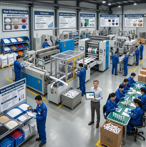
A cosmetic tube sitting on a pharmacy shelf weighs about 12 grams. The raw coil strip that became it weighed roughly 12.5 grams. The difference — that 4% — represents everything the tube mill did: forming, welding, grinding, sizing, straightening, cutting, and verifying through a cascade of quality checkpoints that the finished product meets the dimensional tolerances and surface specifications your customer printed on the drawing.
When a production run produces tubes that fail at the filling line because the OD is 0.2mm oversize, or tubes that trigger a pharmaceutical audit finding because surface roughness exceeds the specified Ra value, the root cause is almost always traceable to one of those 10 production stages — and to a moment where a process parameter drifted outside control limits without being caught.
This guide walks every stage of the tube mill production journey — from raw coil selection through to final cut length verification — with the quality checkpoints, process control principles, and equipment selection insights that separate precision-grade cosmetic and pharmaceutical packaging production from commodity tube manufacturing.

🏭 The 10-Stage Tube Mill Production Journey
Stage 1: Understanding Raw Material Selection and Coil Preparation
What Makes Quality Coil Stock Essential for Tube Production
The quality ceiling of your finished tube is defined at the moment you accept a coil into your production facility. Every dimensional tolerance, every surface specification, every weld integrity requirement downstream depends on the incoming coil material being exactly what the drawing specifies.
For cosmetic and pharmaceutical soft tube production — which primarily uses plastic polymer materials (LDPE, HDPE, PP), aluminum foil-based laminates (ABL), and plastic barrier laminates (PBL) — the incoming material specification is not just a quality document. It is a regulatory document. Any material that contacts the tube’s internal product-contact surface must be traceable to a lot-level material certificate of conformity that confirms chemical composition, food/pharmaceutical contact compliance, and absence of prohibited substances.
Key Considerations for Aluminum vs. Plastic Coil Selection
Performance Characteristics and Application Suitability
Aluminum coil stock (typically 99.5% purity, soft-annealed, 0.10–0.25mm thickness) is used for collapsible aluminum tubes — a format that dominates pharmaceutical ointments, eye drops, and metal-look premium cosmetics. Aluminum’s complete gas and moisture barrier, chemical inertness, and unique tactile experience make it irreplaceable for certain applications. Its weakness: aluminum work-hardens during forming, meaning that tooling wear rates are higher than plastic systems and coil tensile strength consistency is a critical incoming specification.
Plastic laminate coil stock (ABL: aluminum barrier laminate; PBL: plastic barrier laminate) is the dominant format for modern cosmetic soft tube production — accounting for over 60% of global cosmetic tube output. ABL structure combines printed outer LDPE, adhesive layers, aluminum foil core, and inner LDPE product-contact layer, providing near-zero oxygen transmission rate (OTR) while enabling high-quality rotogravure printing directly on the tube sleeve. PBL replaces the aluminum foil core with EVOH barrier polymer — enabling mono-recyclable tube structures that are gaining market share rapidly under EU packaging recyclability mandates.
How Material Thickness and Width Affect Production Efficiency
Coil width determines the circumference of the finished tube — and therefore its diameter. A 25mm diameter tube with a 0.4mm wall thickness requires a coil width of exactly π × (25 + 0.4) × 2 ÷ 2 ≈ 40.0mm, accounting for the overlap seam geometry. Width variation in the coil of ±0.3mm or more creates weld overlap inconsistency that produces seal width variation in the finished tube — a dimensional nonconformance that triggers rejection at the pharmaceutical brand owner’s incoming inspection.
Pre-Production Quality Checkpoints
Visual and Dimensional Inspections of Incoming Coil Stock
Incoming coil inspection for pharmaceutical packaging production must verify: coil width (measured at 5 points across the roll width, tolerance typically ±0.1mm for pharmaceutical grade), material thickness (measured via ultrasonic gauge or contact micrometer at 10 points per coil, tolerance typically ±0.005mm for aluminum, ±0.01mm for laminate), surface condition (visual and tactile inspection for pinholes, scratches, and coating defects), coil splice count and location (splices within a coil create production interruptions; maximum 2 splices per 5,000m coil is a typical pharmaceutical specification), and core diameter (to verify compatibility with the uncoiler mandrel system).
Surface Condition Assessment and Contamination Prevention
The inner surface of a cosmetic or pharmaceutical tube must meet cleanliness requirements consistent with its intended product contact use. For pharmaceutical topical packaging, inner surface cleanliness is typically verified through a rinsate analysis — rinsing the tube interior with a measured volume of extraction solvent and analyzing the extract for heavy metals, particulates, and organic extractables against ICH Q3C guideline limits. Coil stock that enters production carrying lubricant residue, metallic fines from slitting operations, or paperboard dust from interleave layers can introduce contamination that propagates through the entire production run.
📋 Cosmetic & Pharmaceutical Tube Material Comparison
| Material Type | Desempenho da barreira | Typical Thickness | Melhor para | Recyclability |
|---|---|---|---|---|
| Aluminum (soft-annealed) | Absolute barrier | 0.10 – 0.25mm | Pharma ointments, premium cosmetics | High (aluminum) |
| ABL (Laminado de Alumínio com Barreira) | Near-zero OTR | 0.20 – 0.45mm | Sensitive cosmetic actives, OTC drugs | Limited (multi-material) |
| PBL (Laminado com Barreira Plástica) | High (EVOH core) | 0.25 – 0.50mm | Sustainable cosmetic tubes | High (PE recyclable) |
| LDPE / HDPE Extruded | Moderado | 0.35 – 0.80mm | Standard cosmetic, oral care | Excellent (mono-material) |
Stage 2: The Uncoiling Process — Setting the Foundation
How Uncoiling Systems Control Material Feed
Tension Control Technologies in Modern Tube Mills
Tension control — maintaining a consistent pulling force on the material as it travels from the uncoiler to the forming section — is arguably the most underappreciated variable in tube mill process control. Material fed at inconsistent tension enters the forming rolls with varying longitudinal stress, producing width variation in the formed strip edge that directly translates to weld seam width inconsistency in the finished tube.
Modern tube mills use dancer-roll or load-cell-based tension control systems. Dancer-roll systems use a floating roll whose position reflects the current tension — a displacement sensor converts position to a tension signal that drives the uncoiler brake torque. Load-cell systems measure tension directly and are generally more accurate (±2% vs. ±5% for dancer systems) but require more sophisticated electronics. For pharmaceutical packaging applications requiring tight weld seam consistency, load-cell tension control is the preferred specification.
Automated Coil Handling and Safety Features
Manual coil loading — lifting a 200–800 kg coil onto the uncoiler mandrel using overhead crane and slings — is a significant safety exposure and a source of coil edge damage that compromises incoming material. Hydraulic coil car systems that automatically position and mount coils without overhead lifting reduce coil changeover time from 25–40 minutes to 8–12 minutes, while eliminating the edge damage that occurs when coils contact crane slings. At a production speed of 60 tubes/minute, an 8-minute faster changeover translates to 480 additional tubes produced per shift — a productivity gain of 1–2% that compounds across an entire production year.
Quality Checkpoints During Uncoiling
Monitoring Material Straightness and Flatness
Coiled material retains a residual curvature (“coil set”) and may exhibit edge waves or center buckle from non-uniform rolling during manufacture. A coil straightener — typically 5–9 driven rolls in an offset arrangement — applies and releases bending stress in alternating directions to neutralize the coil set. The straightener roll spacing and penetration depth must be calibrated for each material type and thickness; incorrect settings produce a tube that is straight along its axis but has residual stress that manifests as springback during downstream sizing or cutting.
Identifying Surface Defects Early in the Production Cycle
A surface inspection system positioned immediately after the uncoiler — using a line-scan camera with structured LED illumination — can detect pinholes in aluminum foil layers (critical for hermetic barrier performance), printing defects on pre-printed laminate coil, edge irregularities that predict welding problems, and surface contamination from lubricants or foreign particles. Early detection at this stage prevents defective material from advancing through 8 more production stages, where the value-added cost of producing a defective tube is approximately 3–6× the cost of the rejected coil material alone.
Stage 3: The Forming Process — Shaping Raw Material Into Tube Structure
Understanding Cold-Forming Technology in Tube Manufacturing
The Science Behind Material Flow During Forming
Cold forming — shaping material at room temperature through a series of roll stands that progressively bend the flat strip into a circular cross-section — is a continuous deformation process where the material’s crystalline structure is being permanently rearranged with every forming stand. The sequence matters: forming too aggressively at early stands creates edge strain that appears as micro-cracks during later welding; forming too conservatively extends the forming section length and requires more roll stands to achieve the final tube geometry.
For laminate materials (ABL/PBL), the forming process must account for the multi-layer structure’s different material properties in each layer — the outer LDPE is more ductile than the aluminum foil or EVOH barrier core, meaning the forming roll geometry must be designed to distribute bending stress across the composite cross-section without causing delamination between layers. A laminate tube that delaminates during forming shows no visible external defect — but its barrier layer is compromised, and it will fail accelerated stability testing when the cosmetic brand owner puts it through their ICH Q1A validation program.
Tooling Design and Its Impact on Production Quality
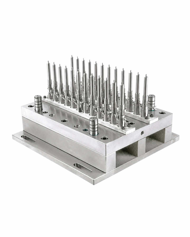
Forming roll tooling is specific to tube diameter and wall thickness — a set of rolls designed for a 25mm diameter tube cannot be used for 35mm production without complete tooling changeover. High-quality tooling is precision-ground to within ±0.005mm of the specified roll geometry and hard-chrome coated to Rockwell C58–62 hardness, providing both the dimensional accuracy and wear resistance needed for multi-million-cycle production runs. Tooling wear is the primary source of progressive dimensional drift in formed tubes — a well-implemented tooling inspection and replacement program, based on actual measured wear data rather than calendar intervals, is the single most effective preventive measure against systematic forming-stage quality degradation.
Critical Quality Checkpoints in the Forming Stage
Measuring Tube Diameter Consistency and Tolerance Compliance
Post-forming dimensional verification uses laser-based non-contact measurement systems that scan the formed tube cross-section 500–2,000 times per second at line speed, providing real-time outer diameter and ovality data. Pharmaceutical packaging specifications typically require OD tolerance of ±0.1mm and ovality (maximum diameter minus minimum diameter at any cross-section) below 0.15mm. Automated feedback from the measurement system to the forming roll pressure adjustment system corrects for thermal expansion, material batch variation, and tooling wear without operator intervention — maintaining specification compliance across an entire 8-hour production shift.
Detecting Micro-Cracks and Material Stress Points
Micro-cracks in formed aluminum tube stock are invisible to the naked eye but grow under the mechanical stress of filling, capping, and consumer dispensing — eventually producing the tube leakage failures that generate product liability claims. Eddy current testing systems positioned at the forming stage exit detect surface-breaking micro-cracks in metallic tubes with a sensitivity threshold of approximately 0.1mm depth. For laminate tube applications, acoustic emission monitoring during forming identifies delamination events as characteristic high-frequency acoustic signatures distinct from the normal forming process noise.
🔧 Cold-Forming Stage: Roll-by-Roll Progression
Each forming stand progressively bends the flat strip toward a circular cross-section. The fin pass stand closes the seam for welding; the QC checkpoint verifies dimensional compliance before the tube advances to the weld station.
Stage 4: The Welding Process — Creating Seamless Joints
▶ Watch: HFI Welded Tube Production Process — How High-Frequency Induction Welding Transforms Strip Material into Finished Tube
Welding Technologies for Cosmetic and Pharmaceutical Tubes
High-Frequency Induction Welding: The Industry Standard
High-frequency induction welding (HFIW) — using electromagnetic energy at 100–500 kHz to induce eddy currents that heat the tube seam edges to welding temperature in milliseconds — is the dominant joining technology for laminate and aluminum tube production. The physics are elegant: only the seam edges are heated (the bulk material remains cool), the weld is achieved by forging the hot edges together under squeeze roll pressure, and the entire process completes at line speeds of 30–120 metres per minute.
For ABL laminate tubes, HFIW heats the aluminum foil layer selectively, which then conducts heat to the surrounding LDPE layers, achieving a homogeneous weld through the full laminate cross-section. HFIW produces lower heat input, better dimensional accuracy, and higher productivity than alternative welding methods for standard cosmetic tube applications — explaining its near-universal adoption in the industry.
Laser Welding for Premium Applications
Laser welding delivers a focused energy beam of precisely controlled power density to the seam interface, achieving fusion without the mechanical contact pressure of HFIW squeeze rolls. The heat-affected zone (HAZ) — the material adjacent to the weld that experiences temperature elevation without actually melting — is typically 30–50% smaller in laser welding than HFIW. For thin-wall aluminum tubes (0.10–0.15mm) used in premium cosmetic applications, this smaller HAZ means less material softening adjacent to the weld, better retention of aluminum’s visual appearance (critical for tubes with bright decorative finishes), and narrower achievable seam widths (0.3–0.8mm laser vs. 1.5–3.0mm HFIW).
The trade-off: laser welding equipment costs 3–5× more than equivalent HFIW systems, and laser beam alignment is more sensitive to machine vibration and thermal drift, requiring more sophisticated process control. For most standard cosmetic and pharmaceutical tube applications, HFIW provides sufficient quality at better economics. Laser welding is the appropriate specification for ultra-thin aluminum tubes, tubes with tight aesthetic seam requirements, and special materials where HFIW’s magnetic field effects are problematic.
Weld Quality Assurance and Testing Protocols
Non-Destructive Testing Methods for Weld Strength
Non-destructive testing (NDT) — testing that evaluates weld integrity without destroying the tube — is essential for pharmaceutical tube production where destructive testing can only verify samples, not 100% of output. Two NDT methods dominate tube mill weld inspection:
Eddy current testing (ECT) induces alternating electromagnetic fields in the tube wall and detects changes in the field pattern caused by discontinuities, cracks, or weld anomalies. ECT systems on modern tube mills scan at line speed, detecting surface and sub-surface defects as small as 0.1mm × 0.5mm with 99%+ sensitivity for through-wall pinholes — the critical failure mode for barrier-tube applications. Eddy current testing for welded and seamless tubes is the reference method in both pharmaceutical packaging quality standards and cosmetic tube industry specifications.
Ultrasonic testing (UT) uses high-frequency sound waves (2–20 MHz) to detect internal weld discontinuities — inclusions, lack-of-fusion zones, and internal cracks that ECT cannot detect because they do not break the surface. UT is slower than ECT (typically used for sampling rather than 100% inspection) but provides more complete characterization of internal weld structure, making it the method of choice for first-article qualification and period audit inspection of pharmaceutical packaging tube welds.
Heat-Affected Zone Management and Material Property Preservation
The HAZ in HFIW aluminum tube production spans approximately 1.5–4mm either side of the weld centerline. Within the HAZ, aluminum that was originally soft-annealed (H0 condition, Vickers hardness ~25–30 HV) experiences partial or complete recrystallization that hardens it to approximately 35–45 HV. This hardened zone is less ductile than the parent material — meaning it is the region most likely to crack during the tube’s downstream processing (shoulder forming) or in-use dispensing cycles. Controlled post-weld cooling rate (achieved by water spray systems positioned 50–100mm after the weld point) limits HAZ hardening by controlling the cooling rate to less than 50°C/second — maintaining HAZ hardness within 10% of parent material.
Stage 5: Post-Weld Grinding and Surface Finishing
The Importance of Weld Bead Removal in Cosmetic Packaging
Grinding Technologies and Precision Control
The weld process creates an external weld bead — a raised ridge of material along the seam that, if not removed, creates a visible external line on the finished tube. For standard cosmetic tubes with full-coverage printing, this bead is acceptable if its height is below 0.05mm; for tubes with clear windows, metallic finishes, or premium unprinted designs, the bead must be ground flush to within ±0.01mm of the surrounding tube surface.
Weld bead grinding uses high-speed abrasive belts or grinding wheels positioned immediately after the weld station, with the tube constrained by precision guides that prevent lateral movement during grinding. Grinding wheel pressure is controlled by a servo actuator responding to real-time feedback from a contact profilometer that measures the remaining bead height. Systems achieving ±0.008mm grinding depth consistency represent current best practice — this level of precision requires grinding spindle vibration isolation, thermal compensation for spindle growth during the shift, and weekly abrasive element inspection.
Dust Management and Environmental Compliance
Grinding generates aluminum or plastic particulate at the micron scale. In a pharmaceutical packaging facility, this particulate is a contamination risk requiring active control: local exhaust ventilation (LEV) systems with extraction velocities of 1.0–1.5 m/s at the grinding point capture approximately 95% of generated particulate. HEPA-filtered air returns prevent recirculation of captured particles into the production environment. Grinding station maintenance records — documenting filter replacement intervals and exhaust flow verification — form part of the contamination control evidence file required by pharmaceutical brand owner qualification audits.
Quality Standards for Surface Finish in Pharmaceutical Packaging
Roughness Measurement and Compliance Verification
Surface roughness — measured as Ra (arithmetic mean roughness, μm) or Rz (mean peak-to-valley height, μm) — determines both the aesthetic quality of printed decoration and the microbial retention risk on the tube’s outer surface. Pharmaceutical-grade cosmetic tube specifications typically require Ra ≤ 0.4μm on the outer surface (equivalent to a bright machined surface) and Ra ≤ 0.8μm on the inner bore (where product contact contamination risk is the primary concern). Profilometer measurements are taken at three circumferential positions per inspection interval — every 500 tubes is typical — with control chart monitoring to detect grinding wheel wear-related drift before it exceeds specification limits.
Contamination Control During Grinding Operations
A contamination event at the grinding stage — where metallic grinding debris enters a tube’s internal bore — is one of the highest-consequence quality failures in pharmaceutical tube production. It is invisible externally, cannot be detected by post-process visual inspection, and may only be discovered when a patient experiences irritation from a topical pharmaceutical product containing metallic particulate. Prevention requires: positive air pressure purging of tube bores during grinding, tube end caps during grinding station transit, and periodic destructive bore flushing tests where random samples are flushed with filtered extraction solvent and the extract is analyzed for particulate count.
Stage 6: Sizing and Calibration — Achieving Dimensional Precision
How Sizing Stations Ensure Consistent Outer Diameter
Mechanical Sizing vs. Hydraulic Sizing Systems
The sizing section is where the tube’s final outer diameter is established with pharmaceutical-grade precision. Post-weld forming irregularities — typically ±0.3–0.5mm OD variation — are corrected by the sizing section to within ±0.05–0.10mm, the tolerance range required for reliable operation on high-speed filling and capping lines.
Mechanical sizing systems use fixed-profile rolls calibrated to the finished tube diameter. They are excellent for high-volume, single-diameter production — setup is simple, maintenance is minimal, and they operate at full line speed without additional process variables. Their limitation: changing tube diameter requires a complete tooling changeover (typically 45–90 minutes), making them economically unsuitable for manufacturers with high product diversity.
Hydraulic sizing systems use servo-controlled roll positioning that can be adjusted in real time via the machine HMI. Diameter changeovers require only parameter entry (under 5 minutes), and the hydraulic pressure control provides superior consistency across varying material hardness — important for manufacturers processing multiple material types on a shared line. Hydraulic systems’ maintenance complexity and higher capital cost are justified when a facility produces 6+ tube diameters with regular changeovers.
Real-Time Adjustment Mechanisms and Feedback Systems
Closed-loop sizing control integrates the downstream laser micrometer measurement (reading OD at 2,000 Hz) with the sizing roll pressure actuators through a digital controller with less than 50ms response time. When a positive OD trend is detected — typically caused by progressive tooling wear or material batch variation — the controller reduces sizing roll gap before the measurement signal reaches the process alarm threshold, maintaining specification compliance without operator intervention. A tube mill running closed-loop sizing control for a pharmaceutical client producing 20 million tubes per year demonstrated a 78% reduction in OD-related rejection events compared to the same line operating with manual OD monitoring and manual sizing adjustment.
Dimensional Verification and Statistical Process Control
Measuring Outer Diameter, Wall Thickness, and Ovality
A complete dimensional verification station for pharmaceutical tube production measures OD at two orthogonal axes simultaneously (detecting ovality), wall thickness at 4 circumferential positions (detecting non-uniform material distribution), and tube straightness deviation. These five measurements, captured at 100% inspection using multi-channel laser systems, generate approximately 50,000 data points per production shift. Managing this data volume requires statistical process control (SPC) software that calculates process capability indices (Cpk) in real time — a Cpk above 1.67 is the standard target for pharmaceutical packaging dimensions, corresponding to fewer than 1 out-of-specification unit per 1 million produced.
Tracking Production Data for Traceability and Compliance Documentation
FDA GMP guidelines for cosmetic packaging and pharmaceutical cGMP under 21 CFR Parts 210/211 require batch-level traceability linking finished tube lots to: raw material coil certificates of analysis, production equipment identification, operator records, in-process measurement data, and final release test results. Modern tube mill data management systems create this documentation automatically from production sensor data, timestamped to the tube lot level — generating a compliant batch record with zero manual transcription and the associated data integrity risk that manual records carry.
📊 Dimensional Tolerance Comparison: Standard vs. Pharmaceutical Grade
| Dimension | Standard Cosmetic | Pharma-Grade | Target Cpk | Measurement Method |
|---|---|---|---|---|
| Outer Diameter | ±0.15mm | ±0.05mm | ≥1.67 | Laser micrometer, 100% |
| Wall Thickness | ±0.03mm | ±0.01mm | ≥1.67 | Ultrasonic, sample |
| Ovality | <0.20mm | <0.10mm | ≥1.33 | Dual-axis laser, 100% |
| Surface Roughness Ra | ≤0.8µm | ≤0.4µm | ≥1.33 | Contact profilometer |
| Cut Length | ±0.5mm | ±0.2mm | ≥1.67 | Laser gauge, 100% |
Stage 7: Tube Straightening — Eliminating Structural Imperfections
Understanding Why Straightening is Critical for Pharmaceutical Applications
A tube with 0.5mm of bow per 100mm of length — well within the tolerance of many non-pharmaceutical applications — creates measurable problems at the pharmaceutical filling line. When a tube with residual bow is loaded into the tube holder of a high-speed filling and sealing machine running at 200 tubes per minute, the bow causes the tube to enter the holder at a slight angle. This 1–2° angular error is amplified as the machine cycles: the tube doesn’t seat properly, the fill nozzle doesn’t center, the bottom seal is applied off-center, and the crimped seal fails the seal integrity test at an elevated rate. A contract pharmaceutical filling line that discovered this correlation tracked 23% of their seal integrity failures to tube straightness non-conformance from their tube supplier — a data point that drove a supplier specification change to ≤0.3mm/300mm straightness requirement.
Straightening Mechanisms and Pressure Application
Rotary straightening uses a series of hyperboloid rolls (rolls with a barrel profile, positioned at an angle to the tube axis) that impart a helical path to the tube. As each point on the tube circumference passes alternately through the high-pressure and low-pressure zones of the roll arrangement, the bending and reverse-bending straightens the tube while maintaining the circular cross-section. The roll angle, roll gap, and tube advancement speed must be precisely calibrated for each tube diameter and wall thickness — incorrect settings either under-straighten (tubes remain bent) or over-straighten (tubes develop surface marks or introduced straightening stress).
Material Property Considerations During Straightening
Straightening aluminum tubes that have already been work-hardened during forming and welding requires careful process control to avoid exceeding the material’s remaining ductility reserve. An aluminum tube that has consumed 60% of its total elongation capacity in forming and welding leaves only 40% for straightening, downstream shoulder forming, and consumer dispensing cycles combined. Straightening machines equipped with torque-monitoring on the drive rollers detect resistance spikes that indicate incipient material fracture — allowing the machine to halt and alert the operator before a material failure propagates into a defective tube that might pass visual inspection but fail catastrophically during consumer use.
Quality Verification After Straightening Operations
Straightness Measurement and Tolerance Compliance
Post-straightening inspection uses laser-based geometric measurement systems that scan the tube on a V-block fixture, measuring the maximum deviation from the ideal centerline along the full tube length. Automated straightness gauges in-line with the production process can inspect 100% of tubes at speeds up to 150 units per minute, sorting nonconforming tubes before they advance to the cutting station. Typical pharmaceutical packaging specifications require straightness ≤0.3mm per 300mm tube length; high-speed filling line specifications sometimes tighten this to ≤0.2mm/300mm for 200+ cycles per minute equipment.
Stage 8: Cutting and Edge Finishing — Final Dimensional Accuracy
Cutting Technologies for Precision Tube Length
Comparing Saw Cutting, Shear Cutting, and Rotary Cutting Methods
Saw cutting (circular saw, tungsten carbide or diamond blade) produces excellent cut quality — square, burr-free ends — but generates kerf (material removed by the saw blade width, typically 1.5–3.0mm) that represents material waste, particularly important when tube material costs $3.00–$5.00/kg. Saw cutting speed limits are approximately 40–60 cuts per minute for quality cosmetic tube applications.
Shear cutting (opposing blades, no kerf) is faster (80–120 cuts per minute) and eliminates kerf waste but produces a cut face with a small shear burr that requires deburring post-cut. For pharmaceutical tubes where the cut end will be sealed, the burr is generally acceptable if it does not exceed 0.05mm height and is not loose (no detached particles risk).
Rotary cutting (a carbide wheel pressed against the rotating tube) combines speed with quality: 100–180 cuts per minute with a nominally burr-free edge on ductile aluminum and laminate materials. It is the dominant cutting method on modern high-speed cosmetic tube mills because it operates without stopping the tube’s forward motion, maintaining continuous production flow without the stop-start dynamics of stationary blade systems.
Achieving Burr-Free Edges Essential for Pharmaceutical Safety
A tube with a sharp burr on its cut end poses two distinct risks in pharmaceutical packaging. First, the burr can lacerate the filling nozzle tip’s elastomeric sealing element, generating rubber particulate that enters the product — a potential foreign body contamination event. Second, the burr can lacerate the consumer’s fingers during tube manipulation, creating a product liability exposure. Deburring stations — using brush, vibratory, or tumbling technology immediately post-cutting — reduce burr height to less than 0.01mm on all cut faces, verified by weekly sample inspection on a tactile comparator surface roughness standard.
Final Quality Checkpoints Before Packaging and Shipping
Length Measurement and Tolerance Verification
Cut length accuracy is determined by the encoder-controlled cut trigger system and the thermal expansion of the tube material. At a production speed of 1.2 m/s line speed, a 1ms timing error in the cut trigger translates to 1.2mm of length error — which is why high-precision cut length systems use tube-contact encoders rather than drive-shaft encoders (which introduce gear train backlash error). Automated 100% length verification using laser gauges installed immediately post-cut, with automated divert of out-of-tolerance tubes to a rejection chute, is standard practice in pharmaceutical packaging tube production. Accepted tolerance range is typically ±0.3mm for standard cosmetic applications, ±0.2mm for pharmaceutical applications with tight fill-volume accuracy requirements.
Edge Quality Inspection and Contamination Prevention
The final pre-packaging inspection station combines automated vision inspection of both tube ends (detecting cracks, burrs, and out-of-round end geometry) with an air purge system that flushes the tube bore with filtered compressed air (filtered to 0.01μm at ISO 8573-1 Class 1) to remove any cutting debris from the tube interior. Tubes that pass all final inspection criteria are automatically counted into pre-set batch quantities and delivered to the packaging station, where they are loaded into protective sleeves or trays and labeled with the batch identification linking them to the production record system.
Stage 9: Quality Control Integration Across All Production Stages

Comprehensive Testing Protocols Throughout the Production Journey
Pressure Testing for Pharmaceutical Packaging Integrity
Pressure testing — sealing one tube end, applying internal air pressure to 150–200% of the tube’s rated burst pressure, and verifying that no leak occurs over a 30-second dwell time — provides direct verification of weld seam structural integrity. While 100% in-line pressure testing is impractical at production speed, automated rotary pressure test systems can test 100% of tubes at speeds up to 60 units per minute, making them viable for pharmaceutical tube production lines with output below this rate. For higher-speed lines, a validated sampling plan (AQL 0.65, Level II per ISO 2859) combined with 100% eddy current weld inspection provides equivalent statistical assurance of population quality.
Cleanliness Verification and Contamination Testing
Particulate cleanliness verification for pharmaceutical packaging tubes follows USP <788> or equivalent standards — rinsing a sample of tubes with a defined volume of WFI (Water for Injection) or pharmaceutical-grade extraction solvent and analyzing the extract by light obscuration particle counting. Pharmaceutical packaging acceptance criteria typically require fewer than 6,000 particles ≥10μm and fewer than 600 particles ≥25μm per tube, consistent with the particulate baseline required to ensure that tube-derived particulate does not compromise the drug product’s particulate cleanliness specification.
Documentation and Traceability Systems
Batch Tracking and Material Certification
Pharmaceutical tube batch documentation links each finished tube lot to: the specific raw material coil lot (with supplier certificate of analysis), the production shift, equipment ID, operator certifications, all in-process measurement data, calibration status of all measurement equipment, and the final release test results. This documentation chain must be retained for the product’s full shelf life plus one year (minimum 2–3 years for most OTC pharmaceutical packaging) and must be producible for regulatory inspection within 24 hours of request. Digital batch record systems integrated with the tube mill’s process data acquisition system generate this documentation automatically, time-stamped and operator-attributed, eliminating the data integrity vulnerabilities of manual paper records.
Statistical Analysis and Process Capability Studies
Controle Estatístico de Processos (SPC) in pharmaceutical tube production uses control charts to monitor process mean and variation for each critical quality attribute in real time. When an Xbar-R chart signals an out-of-control condition — a single point outside 3-sigma control limits, two consecutive points outside 2-sigma limits, or a run of 8 points on one side of the centerline — the production system pauses, alerts the operator, and quarantines product produced since the last confirmed in-control sample for disposition review. This SPC-based approach to quality management, when combined with the measurement infrastructure described in Stage 6, enables the first-pass quality rates above 98% that modern pharmaceutical tube producers target — and that pharmaceutical brand owners specify as a supplier qualification requirement.
📊 Quality Checkpoint Coverage by Production Stage
Welding, sizing, cutting, and final QC stages operate 100% in-line inspection for pharmaceutical-grade tube production. Stages 1–3 and 5 use sampling-based and surface inspection protocols aligned to risk level.
Stage 10: Optimizing Your Tube Mill Investment for Maximum ROI
Selecting the Right Tube Mill Technology for Your Production Needs
Capacity Planning and Production Throughput Optimization
Capacity planning for a tube mill investment must account for actual productive output rather than nameplate speed. A machine rated at 120 tubes/minute at 85% OEE (Overall Equipment Effectiveness — the product of availability rate, performance rate, and quality rate) running 2 shifts per day, 250 production days per year produces:
$$\text{Annual Output} = 120 \times 0.85 \times 60 \times 16 \times 250 = 30{,}600{,}000 \text{ tubes/year}$$Selecting a machine based on nameplate speed rather than OEE-adjusted output leads to systematic capacity shortfalls. The industry benchmark OEE for a well-maintained modern cosmetic tube mill is 82–88%; newly installed lines typically achieve 70–75% OEE in the first 90 days as operators develop process familiarity and preventive maintenance routines are established. Budget for the ramp-up period in your capacity planning rather than assuming nameplate performance from production day one.
Total Cost of Ownership Analysis
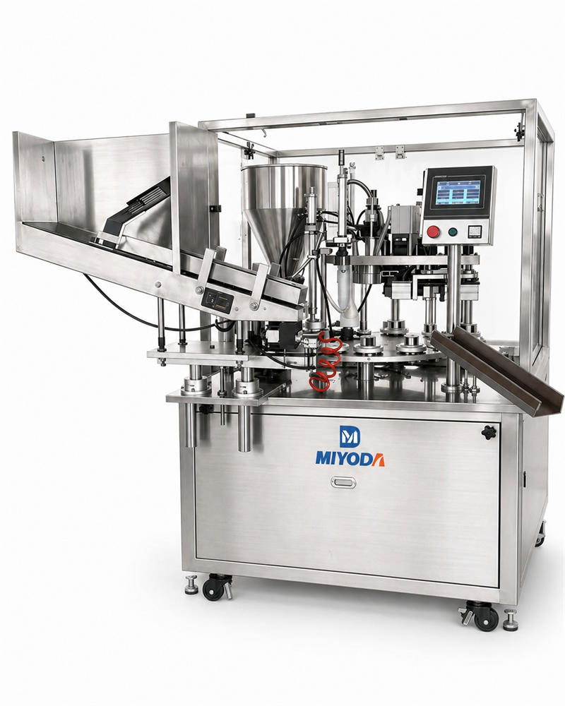
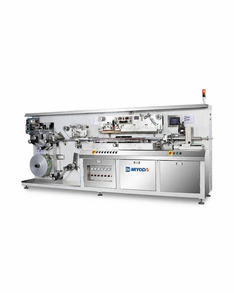
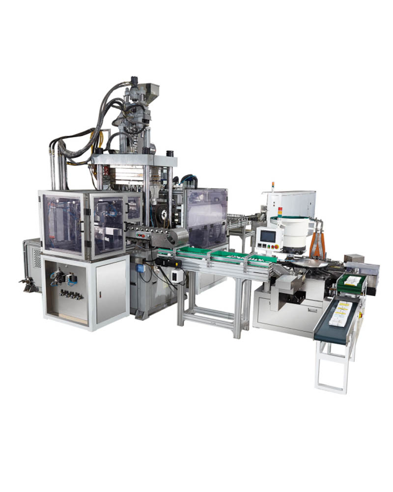
O tube extrusion and production systems offered by Miyoda Packaging Machinery are engineered with TCO as a design consideration — not just output speed. Maintenance-friendly design features (accessible lubrication points, modular tooling systems, standardized electrical components with global spare parts availability) reduce the operational cost difference between a well-supported machine and a poorly supported one from $15,000–$30,000 per year in maintenance labor and downtime — a delta that dwarfs the initial price difference between equipment tiers. When evaluating equipment, always request the maintenance schedule, the annual consumable parts list with current pricing, and references from customers who have operated the same model for 3+ years.
Implementation Best Practices for New Tube Mill Operators
Staff Training and Technical Support Requirements
The most consistent predictor of first-year production performance is not machine specification — it is operator training quality. A study of 24 tube mill installations found that facilities investing in 10+ days of structured on-site commissioning training achieved 76% OEE by week 12, while facilities with 5 days or less of training averaged 58% OEE at the same point — an 18-percentage-point gap representing approximately 3 million tubes per year in lost production capacity at a 120 tubes/minute machine. Training investment is the highest-return capital allocation in the first year of tube mill operation.
Explore Miyoda Packaging Machinery’s full equipment range — from entry-level tube forming systems to fully automated production lines — to identify the configuration that matches your production scale, material type, and quality standard. Their technical team provides application-specific recommendations based on your tube specifications, production volume, and regulatory environment.
Maintenance Protocols and Preventive Care Systems
A properly implemented preventive maintenance program reduces unplanned downtime by 60–70% compared to reactive-only maintenance — translating directly to higher OEE and lower cost per tube produced. The maintenance framework for a tube mill covers: daily (visual inspection, lubrication check, measurement system calibration verification), weekly (forming roll inspection, drive belt tension, cooling system flow rates), monthly (tooling dimensional inspection, hydraulic fluid analysis, electrical panel inspection), quarterly (deep clean, full drive alignment verification, pneumatic system overhaul), and annual (manufacturer service engineer comprehensive inspection, major wear component replacement planning). Documentation of all maintenance activities — including technician identity, parts used, and condition notes — feeds the predictive analytics engine that forecasts the next service requirement before failure, rather than after.
📊 OEE Breakdown: World-Class vs. Industry Average Tube Mill Performance
OEE = Availability Rate × Performance Rate × Quality Rate
World-Class: OEE 85%
Industry Average: OEE 65%
The OEE gap between world-class and industry-average performance represents 8–12 million tubes per year of unrealized production capacity on a 120 tubes/min line — a difference that is primarily driven by maintenance discipline and operator training, not machine capability.
The Path to Premium Tube Production Excellence
The journey from raw coil to finished pharmaceutical-grade tube is not a linear sequence of isolated operations — it is an interconnected system where the quality of every stage’s output defines the constraint for the next. A coil with marginal flatness produces forming variation. Forming variation produces weld seam width inconsistency. Weld inconsistency produces barrier performance variation. Barrier variation produces stability test failures. Each link in that chain traces back to a quality decision made — or not made — at the beginning of the process.
Manufacturers who understand this chain have a fundamental advantage: they know that investing in robust incoming material inspection prevents 5× the cost in downstream failures; that closed-loop sizing control eliminates the OD-related filling line stoppages that cost $800–$1,500 per event; and that a 15-percentage-point OEE improvement through disciplined preventive maintenance adds more annual production capacity than a machine speed upgrade costing $50,000 more.
For equipment buyers evaluating tube production systems — whether for a new cosmetic brand expanding into in-house production, a pharmaceutical contract packager upgrading to pharmaceutical-grade capability, or a distributor advising clients on equipment selection — this production journey framework provides the analytical structure to evaluate equipment not just on nameplate output speed, but on the complete system of process control, quality integration, and operational support that determines real-world performance.
Ready to Transform Your Tube Production?
Schedule a comprehensive consultation with Miyoda Packaging Machinery’s tube mill specialists to discover how our advanced technology can transform your production efficiency, improve product quality, and accelerate your business growth in the cosmetic and pharmaceutical packaging sectors.
📖 Key Technical Terms Glossary
- ABL (Laminado de Alumínio com Barreira)
- A multi-layer tube sleeve material combining printed LDPE outer layer, aluminum foil barrier core, and LDPE inner product-contact layer. Provides near-zero oxygen and moisture transmission. Standard for sensitive cosmetic active ingredients and OTC pharmaceutical tubes.
- Cpk (Índice de Capacidade do Processo)
- A statistical measure of how well a manufacturing process produces output within specification limits, accounting for both process spread and centering. Cpk ≥ 1.67 is the pharmaceutical packaging standard, corresponding to ≤1 defect per million units produced.
- Eddy Current Testing (ECT)
- A non-destructive testing method that induces alternating electromagnetic fields in metallic or conductive tube walls to detect surface and sub-surface defects (cracks, pinholes, weld anomalies) without physical contact or destructive sampling. Standard 100% inspection method for pharmaceutical tube weld verification.
- HAZ (Heat-Affected Zone)
- The region of tube material adjacent to a weld seam that experiences temperature elevation during welding without actually melting. The HAZ has different mechanical properties than the parent material — typically harder and less ductile — and requires controlled cooling rate management to minimize its impact.
- OEE (Eficiência Geral do Equipamento)
- A manufacturing KPI = Availability Rate × Performance Rate × Quality Rate. Represents the percentage of planned production time that generates conforming product at rated speed. World-class tube mill OEE benchmark: 82–88%.
- OTR (Oxygen Transmission Rate)
- The rate at which oxygen permeates through a packaging material under specified temperature and humidity conditions. Critical performance specification for cosmetic and pharmaceutical tubes containing oxidation-sensitive active ingredients. ABL structures achieve OTR below 0.005 cm³/day.
- PBL (Laminado com Barreira Plástica)
- A tube sleeve laminate using EVOH polymer barrier layer instead of aluminum foil — enabling recyclable tube structures while maintaining high barrier performance. Growing rapidly under EU packaging recyclability mandates.
- SPC (Statistical Process Control)
- A method for monitoring and controlling manufacturing processes using statistical techniques and control charts. Detects process shifts and trends in real time, enabling corrective action before specification limits are breached. Required for pharmaceutical packaging quality management systems.
Perguntas frequentes
What is the difference between high-frequency induction welding and laser welding for tube production?
High-frequency induction welding (HFIW) uses electromagnetic energy at 100–500 kHz to heat tube seam edges by inducing eddy currents, then forges the hot edges together under squeeze roll pressure. It is cost-effective, operates at 30–120 m/min line speed, and is the dominant method for standard cosmetic and pharmaceutical laminate tube production. Laser welding delivers a focused energy beam to the seam interface, producing a 30–50% smaller heat-affected zone, narrower weld seam (0.3–0.8mm vs. 1.5–3.0mm for HFIW), and superior aesthetics for thin-wall aluminum tubes with premium finishes. Laser systems cost 3–5× more than HFIW and are specified for ultra-thin aluminum tubes, tubes with stringent aesthetic seam requirements, or special materials where HFIW’s magnetic field characteristics are problematic.
How do modern tube mills maintain consistent wall thickness throughout the production process?
Advanced tube mills employ real-time measurement at multiple production stages: ultrasonic wall thickness measurement at 4 circumferential positions post-forming (detecting non-uniform material distribution), laser OD measurement at 2,000 Hz during sizing (with closed-loop feedback to sizing roll actuators), and multi-channel laser cross-section scanning post-sizing. When measurement data indicates wall thickness drift — from tooling wear, material batch variation, or thermal expansion — automated feedback systems adjust forming and sizing parameters within 50ms response time. The target for pharmaceutical-grade tubes is wall thickness tolerance of ±0.01mm, maintained at Cpk ≥ 1.67 throughout the production run without manual operator intervention.
What quality checkpoints are essential for pharmaceutical packaging tubes?
A pharmaceutical-grade tube quality system requires 9 integrated checkpoint stages: (1) incoming coil dimensional and surface inspection with lot traceability, (2) post-uncoiling straightness and surface defect detection, (3) post-forming OD, wall thickness, and ovality verification, (4) 100% weld integrity verification by eddy current testing, (5) post-grinding surface roughness measurement and contamination check, (6) 100% OD and straightness verification at sizing with SPC monitoring, (7) post-straightening geometric compliance, (8) 100% cut length and edge quality verification, and (9) final pressure testing and cleanliness verification with batch documentation. Each checkpoint generates data that links to the batch record, providing the traceability chain required by FDA 21 CFR Parts 210/211 and EU GMP Annex 1.
How does straightening technology prevent damage to tubes during the process?
Modern rotary straightening systems use hyperboloid rolls positioned at a calculated angle to the tube axis, imparting a helical path that applies alternating bending and reverse-bending stress to neutralize residual bow. The critical control variable is roll penetration depth — the amount of overbend applied at each roll. This is calculated from the tube material’s elastic modulus and yield strength to ensure sufficient plastic deformation for straightening without exceeding the material’s remaining ductility budget. Torque-monitoring sensors on drive rolls detect resistance spikes (indicating incipient material fracture) and halt the machine before a defective tube is produced. For aluminum tubes, the straightening process is designed to consume less than 15% of the material’s remaining elongation capacity, preserving sufficient ductility for shoulder forming and consumer dispensing cycles.
What are the key differences between mechanical and hydraulic sizing systems?
Mechanical sizing systems use fixed-profile rolls calibrated to a specific tube diameter. They excel in high-volume, single-diameter production: maintenance is simple, setup is fast once tooling is in place, and they operate at full line speed with no additional process variables. Diameter changeover requires physical tooling exchange (45–90 minutes). Hydraulic sizing uses servo-controlled roll positioning adjustable via machine HMI parameters — diameter changeovers take less than 5 minutes, making them economically superior for facilities producing 6+ tube diameters with regular changeovers. Hydraulic systems provide superior pressure consistency across varying material hardness batches, reducing sizing-related OD variation from material batch changes by approximately 40% versus fixed mechanical sizing. Their trade-off: higher capital cost ($25,000–$60,000 premium), more complex maintenance, and hydraulic fluid management requirements.
What production capacity should I choose for my tube mill investment?
Capacity selection should be based on OEE-adjusted annual output projection, not nameplate speed. Calculate: (target tubes/year) ÷ (operating hours/year × OEE target) = required tubes/minute. Apply 85% OEE for a well-maintained modern system, 75% for first-year ramp-up. Add 20–30% capacity buffer for growth and demand peaks. Typical categories: entry-level (30–60 tubes/min, 5–15M units/year), mid-range (60–120 tubes/min, 15–35M units/year), high-speed (120–300+ tubes/min, 35–100M+ units/year). Consult with Miyoda Packaging Machinery’s application team to match specific tube specifications (diameter, material, wall thickness) to realistic throughput projections for your production environment.
What is the total cost of ownership for a tube mill beyond the initial purchase price?
Total cost of ownership over 5 years for a mid-range cosmetic tube mill ($180,000–$250,000 purchase price) typically includes: maintenance and spare parts at 2–4% of equipment value annually ($18,000–$40,000 over 5 years), tooling replacement ($12,000–$25,000 over 5 years), energy consumption ($12,000–$20,000/year depending on system efficiency and local rates), operator labor ($50,000–$65,000/operator/year, with 1–2 operators per line), facility costs (space, utilities infrastructure, HVAC), and quality system investment (measurement equipment, consumables, calibration). Modern energy-efficient systems with variable frequency drives reduce energy consumption by 20–30% versus legacy designs — a $3,000–$6,000 annual operating cost advantage that compounds over the machine’s 10–15-year service life.
How do I evaluate the technical support and training provided by tube mill manufacturers?
Evaluate technical support on five criteria: (1) initial training depth — is commissioning training 5 days or 10+ days, and is it conducted by a production engineer or a sales representative?; (2) response time commitment — do they offer a specific contractual MTTR (mean time to respond) for production-critical breakdowns?; (3) spare parts availability — what is the lead time for the 10 highest-wear components, and do they stock them locally or ship from factory?; (4) remote diagnostics — do they offer live remote connection to diagnose control system issues in real time, reducing engineer travel delay?; and (5) customer references — speak with three clients in your production volume range specifically about post-sale support quality at 6, 12, and 24 months after installation, not just during the commissioning period.
What regulatory certifications and compliance standards should my tube mill meet?
Essential certifications depend on your target market and product type. CE marking is mandatory for equipment placed on the EU market, verifying conformity to Machinery Directive 2006/42/EC safety requirements. ISO 9001 certification of the equipment manufacturer verifies their quality management system — a prerequisite for pharmaceutical brand owner supplier qualification. For pharmaceutical packaging applications, the equipment must be designed to support IQ/OQ/PQ validation documentation requirements: the manufacturer should provide Installation Qualification protocol templates and documented equipment specifications that support your Operational Qualification testing. Specific pharmaceutical markets may require additional documentation — FDA 21 CFR Part 11 compliance for electronic records (if applicable), MDSAP certification for medical device adjacent applications, and FDA container-closure system guidance compliance documentation for pharmaceutical packaging equipment.
Can tube mills be customized for specific cosmetic or pharmaceutical applications?
Yes — modern tube mill systems offer extensive application-specific customization. Forming and sizing tooling is manufactured to specific tube diameters (typically 10–100mm+ range) and wall thicknesses. Welding systems are selected and configured for specific material types — ABL laminates require different HFIW coil geometry than aluminum or PBL structures. Grinding systems are specified for the surface roughness requirement of the intended application — pharmaceutical-grade cosmetic tubes require finer finish capability than standard cosmetic applications. Quality system integration (measurement range, inspection frequency, documentation system interface) is configured to the customer’s regulatory compliance requirements. For highly specific pharmaceutical applications — particularly narrow-tolerance tubes for high-speed automated filling lines — first-article production samples are produced and measured against the final tube specification before production tooling is committed, validating that the custom configuration achieves the required Cpk values.
What maintenance protocols are necessary to keep a tube mill operating efficiently?
A comprehensive preventive maintenance program for a tube mill covers five frequency tiers: daily (visual inspection of all forming, welding, and sizing stations; lubrication of designated points; verification of measurement system zero calibration — 30 minutes); weekly (forming roll surface inspection for wear or damage; drive belt/chain tension; cooling water system flow rate verification; grinding wheel condition — 1.5–2 hours); monthly (tooling dimensional verification against nominal; hydraulic fluid level and condition; electrical panel and cable inspection; compressed air filter replacement — 3–4 hours); quarterly (hydraulic system oil analysis; deep clean and regreasing of all linear motion systems; full drive alignment verification — 6–8 hours); and annual (manufacturer service engineer comprehensive inspection; scheduled replacement of all high-wear components per the manufacturer’s life-cycle data; control system software update verification — 1–2 days). Properly implemented preventive maintenance reduces unplanned downtime by 60–70% and extends equipment service life by 5+ years beyond what reactive-only maintenance achieves.
What are the most common production challenges when starting tube mill operations, and how can they be avoided?
The five most consistently reported first-year challenges are: (1) forming roll setup errors causing systematic OD drift — mitigated by structured tooling setup training with measurement verification at each step; (2) weld power setting mismatch with actual material batch properties — mitigated by establishing a material characterization protocol and weld power range chart specific to each material supplier lot; (3) contamination events from grinding operations — mitigated by establishing bore purge procedures and periodic bore rinse particle count testing; (4) OEE underperformance versus projections — mitigated by realistic 75% first-quarter OEE budgeting and a structured improvement program targeting the top 3 downtime causes each month; and (5) documentation gaps that create compliance audit findings — mitigated by implementing electronic batch records from production day one, not as a planned future upgrade. Manufacturers who treat these five risk areas as implementation prerequisites rather than operational learning experiences consistently achieve specification compliance within the first 90 days of production.
How do I optimize production efficiency and reduce waste in tube manufacturing?
Production efficiency optimization in tube manufacturing follows a hierarchy of interventions from highest-impact to lowest. First: eliminate unplanned downtime through preventive maintenance — each unplanned stop costs 8–25× more per hour than a planned maintenance interval. Second: achieve first-pass quality above 95% by optimizing process parameters for each material type and monitoring Cpk in real time — scrap reduction below 2% saves $15,000–$40,000/year in material cost at mid-range production volumes. Third: reduce changeover time for multi-diameter operations through quick-change tooling systems and pre-staged changeover carts — every 15 minutes saved per changeover adds 1,500–2,500 tubes in annual production at 100 tubes/minute. Fourth: implement raw material incoming control that quarantines out-of-specification coils before they enter production — preventing coil-related production issues saves an average of 2.5 hours of troubleshooting and rework time per occurrence. Modern tube mills with real-time analytics, when operated with disciplined process control, routinely achieve 95%+ first-pass quality rates and material waste below 2%.
What data and analytics capabilities should modern tube mills provide for business intelligence?
A data-capable modern tube mill should provide, at minimum: real-time production dashboard (tubes/minute actual vs. target, OEE %, active downtime reason code); quality data stream (dimensional measurements at every checkpoint, control charts with alarms, Cpk trending over time); material consumption tracking (coil length consumed, scrap weight per shift, material efficiency %); maintenance intelligence (time since last PM for each component, alert queue for upcoming service intervals, unplanned stop frequency by root cause); and batch documentation (automatic batch record generation linking all production data to the lot identifier and customer order). Integration with MES (Manufacturing Execution Systems) or ERP systems via OPC-UA or API allows this production data to flow into enterprise reporting, inventory management, and customer documentation systems automatically — eliminating manual data transcription and creating the audit-ready documentation environment that pharmaceutical brand owners require during supplier qualification visits.
How do I ensure my tube production meets pharmaceutical packaging standards and regulations?
Achieving and maintaining pharmaceutical packaging compliance for tube production requires four parallel workstreams that must be established before commercial production begins. (1) Material qualification: every raw material must have a supplier certificate of analysis, be characterized for relevant migration and extractables at the intended use conditions, and be listed in an approved material specification with change-control procedure. (2) Process validation: IQ/OQ/PQ studies must document that the equipment is correctly installed, operates within process parameters that produce conforming product, and consistently delivers specification-compliant tubes under normal production conditions with commercial materials and operators. (3) Quality system documentation: SOPs for every production stage, training records for every operator, calibration records for every measurement device, and batch records linking raw materials to finished lot identities — all retained for the required period and producible within 24 hours of regulatory request. (4) Ongoing monitoring: SPC control charts for critical dimensions, periodic cleanliness testing, annual product contact extractables verification, and internal audit programs that identify compliance gaps before external audits do. Manufacturers who build these four systems from the beginning — rather than retrofitting them after initial production — consistently pass first-time pharmaceutical brand owner qualification audits without major findings.