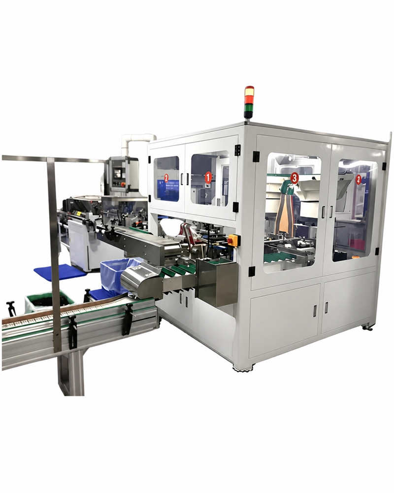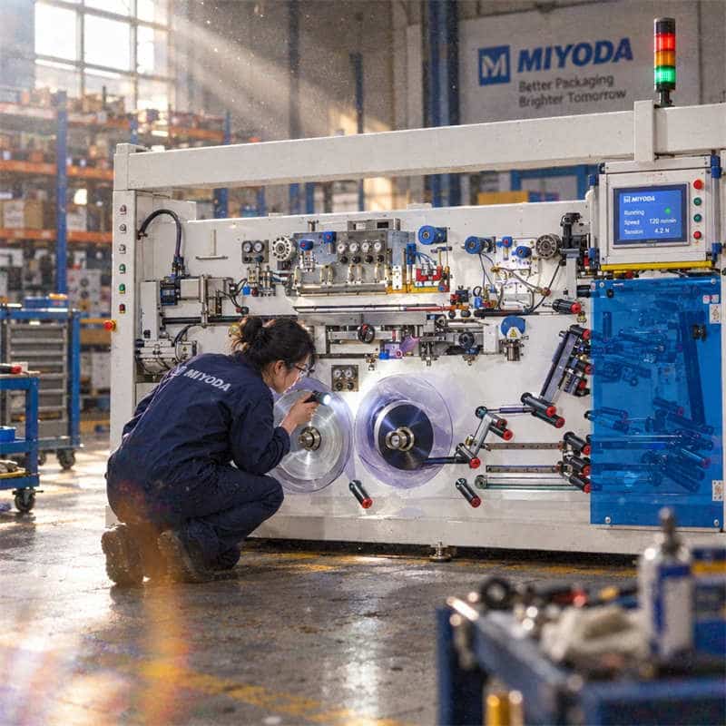
Why Lamination Quality Matters in Cosmetic and Pharmaceutical Packaging
In cosmetic and pharmaceutical soft tube production, lamination is not a background process. It is the step that determines whether your tube holds up on the retail shelf, maintains its barrier integrity through a six-month supply chain, and passes the quality checks your pharmaceutical clients require before they approve a production batch.
When lamination works correctly, it is invisible — the tube looks clean, bonds are tight, and nothing peels, bubbles, or wrinkles. When it fails, the consequences are immediate and costly: rejected batches, production stoppages, expensive material waste, and in regulated pharmaceutical environments, documentation events that can delay product release by days or weeks.
The operators and production managers who handle lamination issues most efficiently are not the ones who react fastest when something goes wrong. They are the ones who understand what is happening inside the machine well enough to catch the early warning signs — and intervene before a minor process drift becomes a full production failure.
This guide walks through the five most common lamination defects encountered in cosmetic and pharmaceutical soft tube production, gives you a structured diagnostic path for each, and closes with an environmental, operational, and maintenance framework that protects your line from recurring issues.
Who this guide is for: Production managers, machine operators, quality supervisors, and distributors operating or evaluating lamination machines for cosmetic or pharmaceutical soft tube manufacturing. Whether you are troubleshooting an active defect or building a preventive maintenance plan, this guide gives you the practical framework to act on.
Understanding the Lamination Process: A Quick Refresher for Optimal Performance
Before diagnosing defects, it helps to have a clear picture of what is happening at each stage of the lamination process — because most defects have their root cause at a specific process stage, even if the symptom appears downstream.
A typical dry or solventless lamination line for cosmetic soft tube substrate runs through five functional stages:
1. Substrate feeding (unwind station): The primary substrate film — typically a PE film, aluminium foil, or a pre-printed outer layer — unwinds from a roll under controlled tension. Tension at this stage sets the baseline stress state of the entire web. Any instability here propagates through every downstream stage.
2. Adhesive application: The adhesive — solventless polyurethane in most modern cosmetic tube lamination lines — is metered and applied to one or both substrates through a gravure roll or slot-die coater. The coat weight (grams per square metre, g/m²) determines bond strength. Too little adhesive produces weak bonds; too much produces bleed-through and surface contamination.
3. Nip lamination: The two substrate layers are brought together and pressed between heated rollers (the “nip”). Pressure and temperature at the nip drive the adhesive into contact with both substrate surfaces and initiate the bonding reaction. This is where bubbles, uneven bonding, and alignment defects most commonly originate.
4. Curing (dwell time or oven): The bonded laminate travels through a curing zone — either a heated oven tunnel for solvent-based adhesives or a controlled-temperature dwell section for solventless systems — where the adhesive reaches its final cross-linked state and bond strength develops to specification.
5. Winding (rewind station): The finished laminate rolls onto a rewind spool under controlled tension. Incorrect tension at this stage can cause wound-roll pressure that distorts the cured laminate structure, producing edge lifting or residual stress that creates apparent delamination when the roll is unwound at the tube-forming stage.
Glossary: Web tension — The force applied to the substrate film along its machine direction as it travels through the lamination line. Measured in Newtons per metre width (N/m) or pounds per linear inch (PLI). Incorrect web tension is the root cause of the majority of lamination defects, including wrinkling, tunnelling, and registration errors.
Understanding which stage each defect originates from shortens diagnostic time from hours to minutes.
Issue #1: Uneven Lamination — Causes and Immediate Corrective Actions
What It Looks Like
Uneven lamination appears as visible variation in bond quality across the width of the laminate — one edge bonds cleanly while the other shows lifting, milkiness, or incomplete wetting. In a finished tube, it shows up as inconsistent barrier performance, print distortion at the tube shoulder, or delamination that occurs selectively at one side of the tube body.
Root Causes
Three mechanical conditions produce uneven lamination, and they are often present simultaneously:
Roller misalignment: When the nip rollers are not perfectly parallel, they apply higher pressure to one side of the web than the other. Even a 0.1 mm parallelism error across a 300 mm web width creates a measurable pressure gradient that produces differential adhesive penetration and uneven bond strength.
Pressure imbalance across the nip: Even on correctly aligned rollers, worn bearings, uneven roller surface hardness, or incorrect pneumatic pressure settings on one side of the nip beam produce lateral pressure variations. As Oasis Alignment’s guide on coating and laminating line misalignment notes, uneven cross-machine load cell readings are one of the earliest measurable indicators of nip alignment problems — often appearing before visible defects do.
Inconsistent web tension across the width: If the unwind roll has a conical profile (more material on one edge than the other due to poor winding), the web will track diagonally and carry uneven tension across its width as it enters the nip. This is particularly common with aluminium foil substrates, which have low stretch tolerance and amplify small tension differentials.
Step-by-Step Diagnostic Procedure
- Stop the machine at production speed and remove the substrate web from the nip.
- Using a dial gauge, measure roller parallelism at five points across the nip width. Acceptable tolerance is ±0.05 mm for precision cosmetic lamination.
- Check pneumatic pressure on both sides of the nip beam — verify that both sides read the same pressure value as displayed on the machine’s HMI.
- Inspect the unwind roll profile visually. A roll with visible edge taper or eccentric winding requires replacement before the diagnostic is meaningful.
- Run a 5-metre test web at reduced speed, mark the web at the nip entry with a transverse line, and examine how the line tracks through the nip exit — any lateral displacement indicates nip alignment error.
Preventive Routine
Nip roller parallelism should be checked and recorded every 250 production hours. Bearing condition inspection — checking for play, noise, or heat — should be part of the weekly maintenance routine. Document results in the machine’s maintenance log to identify gradual drift before it produces visible defects.
Issue #2: Poor Adhesive Bonding — Solving Delamination and Weak Seals
What It Looks Like
Poor adhesive bonding presents as peeling between laminate layers — either immediately after production (indicating a process fault) or after 24–72 hours of curing (indicating an incomplete cross-linking reaction). In pharmaceutical tube production, it can also appear as failing peel strength tests that produce results below the specification minimum of 2.5 N/15mm.
A delaminating cosmetic tube is not just a quality problem. In pharmaceutical topical products, delamination creates micro-channels between laminate layers that compromise the barrier against oxygen and moisture — potentially degrading the active ingredient before the patient uses the product.
Root Causes
Incorrect adhesive mix ratio: Solventless polyurethane adhesives consist of two components (isocyanate and polyol) that must be blended at a precise ratio — typically stated as a weight ratio on the adhesive technical data sheet (TDS). A ratio deviation of more than ±3% from specification produces a stoichiometrically imbalanced polymer network that cannot reach full cross-link density, resulting in permanent bond strength deficiency.
Insufficient curing: Even a correctly mixed adhesive requires adequate time and temperature to complete its cross-linking reaction. If laminated substrate is wound under high tension before cure is complete, the wound-roll pressure creates shear stress on the partially cured bond that prevents full cross-linking from occurring.
Substrate surface contamination: Release agents, silicone residues from roll storage, or skin oils transferred during manual handling create a boundary layer between the substrate surface and the adhesive. The adhesive bonds to the contaminant rather than to the substrate — and the contaminant bond fails. As documented in Packaging Impressions’ delamination prevention guide, surface contamination is one of the three most common root causes of delamination in flexible packaging lamination.
Low substrate surface energy: PE and polypropylene substrates have naturally low surface energy — typically 29–33 dynes/cm — which is insufficient for reliable adhesive wetting. Corona treatment raises surface energy to the acceptable range of 38–42 dynes/cm.
Glossary: Dyne level — A measurement of a substrate’s surface energy, expressed in dynes per centimetre (dynes/cm). Higher surface energy means the surface is more receptive to adhesives, inks, and coatings. Dyne pens — a set of calibrated felt-tip markers containing fluids of known surface tension — are used for rapid field measurement of surface energy on substrates before lamination.
Diagnostic Procedure
- Viscosity check: Measure the mixed adhesive viscosity with a Brookfield or cup-and-ball viscometer immediately before use. Compare to the TDS specification at your operating temperature. A deviation of more than 15% from specification indicates an incorrect mix ratio or aged adhesive.
- Dyne level check on substrate: Apply a dyne pen in the 38 dynes/cm range to the substrate surface. If the fluid beads rather than spreading, surface energy is below threshold and corona treatment is required or the treatment level has degraded.
- Curing time verification: Cut a 15mm×100mm peel test strip from the freshly laminated substrate and conduct a T-peel test at 300mm/min. Record force. Repeat after 24 hours. If 24-hour peel strength is not at least 40% higher than the immediate peel strength, curing is progressing abnormally slowly — check oven temperature calibration.
- Coat weight check: Weigh a 100mm×100mm sample of each substrate before and after adhesive application. Calculate coat weight in g/m². Compare to TDS specification (typically 2.0–4.5 g/m² for solventless adhesives in cosmetic lamination).
Adhesive Storage and Handling Protocol
Store adhesive components at 18–25°C in sealed containers away from direct sunlight. Never use adhesive from a container that has been open for more than 4 hours without re-sealing. Mix only the volume you will consume within the pot life specified on the TDS — for most solventless cosmetic lamination adhesives, this is 60–90 minutes at 40°C working temperature.
Issue #3: Wrinkling or Creasing in the Laminate — Preventing Material Distortion
What It Looks Like
Wrinkles appear as longitudinal or diagonal fold lines in the laminate web, visible on the finished substrate roll and reproduced on every tube formed from that roll. Light wrinkling at the web edges may be trimmed away, but wrinkles in the body of the web produce visible fold lines on printed tube graphics — a defect that is immediately visible to consumers and typically triggers rejection by brand clients at incoming inspection.
Root Causes
Web wrinkling in lamination has seven established root causes, as documented in the web handling engineering literature from Maxcess International’s wrinkling analysis. For cosmetic soft tube lamination, the three most common are:
Tension imbalance between machine drive zones: When the tension set at the nip exit is lower than the tension carried from the nip entry, the web goes into compression immediately after the nip — and a web in compression wrinkles. This typically happens when the rewind tension is set too low or when a downstream tension break (such as a driven idler roller with insufficient grip) allows the web to go slack.
Misaligned guide rollers: An idler roller whose axis is not perpendicular to the machine direction deflects the web laterally as it passes over the roller, creating a localised tension gradient across the web width. The high-tension edge stretches; the low-tension edge buckles. The result is a diagonal wrinkle originating at the roller and propagating downstream.
Improper dancer roll function: The dancer roll — a free-rotating, weighted or pneumatically loaded roller that floats on the web — acts as a tension buffer between machine drive zones. If the dancer roll is sticking (due to bearing wear or contamination), it loses its buffering function and tension spikes propagate through the machine, causing periodic wrinkling that correlates with the dancer roll’s oscillation frequency.
Diagnostic Checklist
- ✅ Using a straight edge, verify that each guide roller between the unwind and rewind stations is perpendicular to the machine direction. Maximum allowable skew: 0.5 mm across the roller face width.
- ✅ Manually rotate the dancer roll by hand. It should move freely with no sticking or rough spots. Check bearing condition at both ends.
- ✅ Review the tension controller setpoints for each drive zone. The tension setpoint should increase progressively from unwind to rewind — a flat or inverted tension profile between zones will produce wrinkles.
- ✅ Observe the web path in the machine at running speed from the operator side. Any lateral web movement (the web drifting left or right) indicates a misaligned or worn guide roller that needs correction.
Real-Time Monitoring Recommendation
On machines running at speeds above 100 m/min, manual tension monitoring between zones is insufficient to catch tension spikes before they produce wrinkles. Load cell-based tension measurement with real-time display on the machine HMI allows operators to see tension variations as they occur. If your machine does not have load cell tension feedback across all drive zones, this is an upgrade that typically pays back in reduced waste within 3–6 months of installation.

Web tension is not one number — it is a profile across multiple drive zones. Wrinkling almost always traces back to a tension transition point where the web goes from high tension to low tension and buckles.
Issue #4: Bubbles or Voids in the Laminate — Eliminating Trapped Air
What It Looks Like
Bubbles appear as visible, dome-shaped protrusions on the laminate surface — individual air pockets trapped between the bonded substrate layers. Voids are similar but appear as flat, cloudy areas where adhesive contact is absent rather than where air is actively trapped. Both defects compromise barrier integrity and produce cosmetically unacceptable finished tubes.
In high-barrier pharmaceutical tubes, even a single void of 5 mm diameter in the body laminate creates a direct oxygen permeation path that can reduce the barrier effectiveness of an ABL structure by 60–80% at that location.
Root Causes
Insufficient nip pressure: When nip pressure is too low, the adhesive film between the two substrates cannot fully wet both surfaces before the web exits the nip. Air remains trapped in areas of incomplete wetting. As documented in Sinstar’s troubleshooting analysis for solventless lamination, the most common single cause of bubble defects in solventless cosmetic lamination is nip pressure below the minimum threshold for the substrate combination in use.
Excessive laminating speed relative to adhesive viscosity: At higher speeds, the dwell time inside the nip decreases. If the adhesive viscosity is too high to fully spread across both substrate surfaces within this shortened dwell time, air pockets form at the leading edge of adhesive flow zones. This is why bubble defects often appear or worsen when speed is increased without a corresponding reduction in adhesive viscosity (through temperature adjustment) or increase in adhesive coat weight.
Substrate surface moisture: Water vapour at the substrate surface vaporises under the heat and pressure of the lamination nip, creating small gas pockets that become bubbles in the bonded structure. PE films stored in humid conditions or removed from packaging before reaching ambient temperature are the most common source of substrate surface moisture in cosmetic lamination operations.
Step-by-Step Corrective Actions
- Increase nip pressure in 5% increments while running at your standard production speed. After each increment, cut a test sample and inspect under diffuse lighting. Stop when bubble count drops below your specification limit.
- Reduce laminating speed by 10% and check whether bubble count decreases. If it does, the issue is adhesive spread rate at current speed — either increase adhesive temperature (to reduce viscosity) or accept the lower speed as the process limit for your current substrate and adhesive combination.
- Allow substrate rolls to condition for at least 4 hours at production room temperature before loading into the machine. This eliminates surface moisture from cold storage conditions.
- Check nip roller surface condition: Damaged, scored, or contaminated roller surfaces create localised pressure voids that produce systematic bubble patterns. A nip roller with a groove or contamination spot will produce a repeating bubble pattern at the pitch corresponding to the roller circumference.
Issue #5: Substrate Slippage or Misregistration — Ensuring Precision Alignment
What It Looks Like
Misregistration in lamination shows up as offset between the printed outer layer and the barrier substrate underneath — the design appears shifted, or a specific colour or graphic element is not aligned with its intended position on the tube body. In multi-layer substrates, it can also appear as one layer tracking at an angle relative to the others, causing a diagonal stripe effect visible on finished tubes.
For cosmetic brands with precise visual identity requirements, misregistration of more than ±0.5 mm is typically a rejection criterion at brand owner incoming inspection.
Root Causes
Worn web guiding sensors: Edge-sensing or line-sensing web guides use optical or ultrasonic sensors to detect the lateral position of the web edge or a register mark. Contaminated sensor lenses, sensor drift over time, or sensors set to the wrong sensitivity level allow the web to wander laterally without triggering a correction — producing progressive misregistration that worsens through a production run. Per the r2r.tech web guiding system technical guide, sensor contamination is the most frequent cause of web guiding system underperformance in flexible packaging operations.
Inconsistent web tension between laminate layers: In a two-substrate lamination (outer print film over barrier substrate), if the two webs carry different tension values into the nip, they travel at slightly different effective speeds — causing progressive lateral displacement between the layers as the run continues.
Faulty or worn web grippers: On machines with pin-registered or clip-registered substrate feeding, worn grippers allow the substrate to micro-slip in the machine direction, producing registration errors that are inconsistent and difficult to correlate with a single mechanical root cause.
Registration Calibration Procedure
- Clean all web guide sensors with a lint-free cloth and approved optical cleaner. Verify sensor response by manually moving the web edge through the sensor detection zone and confirming that the guide actuates in response.
- On a two-web laminator, stop the machine and align both web edges manually to the machine centreline. Set both tension controllers to equal values and run a 2-metre test strip. Measure the lateral offset between the two webs at the laminate exit.
- If offset is present with equal tension settings, check for diameter difference between the two unwind rolls — a larger diameter roll on one station feeds more material per revolution at the same motor speed, effectively running faster than the smaller roll and causing progressive misregistration.
- For machines with motorised web guides, verify that the guide response speed (the rate at which the guide actuates when a deviation is detected) is appropriate for your production speed. An under-responsive guide allows the web to travel several metres off-course before correction begins.
Environmental and Operational Factors That Impact Lamination Quality
The Production Environment Is Part of Your Process
Many lamination defects that appear to be machine problems are actually environment problems — the machine is functioning correctly, but the conditions around it are preventing the process from running within specification.
The three environmental variables with the most direct impact on cosmetic soft tube lamination quality are:
Temperature: The lamination room should be maintained at 20–25°C (68–77°F). Below 18°C, solventless adhesives increase in viscosity above their normal operating range, requiring higher coating temperatures and producing application inconsistency. Above 28°C, pot life decreases significantly — a solventless adhesive that has a 90-minute pot life at 40°C working temperature may have only 45 minutes at a 35°C ambient, leading to partially gelled adhesive being applied during longer production runs.
Relative humidity: The optimal range for lamination operations in cosmetic and pharmaceutical tube production is 45–60% RH. Below 40% RH, static charge builds up on PE and aluminium foil substrates, causing web tracking instability, substrate-to-roller adhesion, and operator safety hazards from electrostatic discharge. Above 65% RH, moisture absorption by hygroscopic substrate layers (particularly paper-based components and some specialty films) increases before lamination — creating the substrate moisture conditions that produce bubbles during the nip process. For pharmaceutical-grade production environments, cleanroom guidelines published by CSI Testing specify temperature ranges of 68°F–72°F and humidity of 30–60% RH for GMP-compliant packaging production environments.
Airborne particulates: Dust particles on the substrate surface or in the adhesive coating system produce pinhole defects and point contamination in the laminate. A lamination machine operating in an open-floor manufacturing environment without particulate control will produce background defect rates 3–5× higher than the same machine operating in a controlled environment with positive air pressure and HEPA filtration.
Practical Facility Recommendations
- Install temperature and humidity data loggers at the machine unwind station, adhesive mixing area, and curing zone. Log continuously and review trends weekly — deviations correlate directly with batch quality variation.
- Position the lamination machine away from external doors, loading dock entrances, and HVAC supply vents that introduce uncontrolled temperature or humidity.
- If operating in a geographical location with significant seasonal humidity variation, install a dedicated dehumidification system for the lamination area rather than relying on the building’s general HVAC.
When to Call for Technical Support: Recognising Critical Failures
Not Every Problem Has a Self-Diagnostic Solution
Most of the lamination defects covered in this guide — uneven bonding, wrinkling, bubbles, misregistration — have identifiable mechanical or process causes that a trained operator can diagnose and correct. But some fault conditions indicate hardware damage, control system failure, or process deterioration that requires manufacturer-level support to resolve safely and correctly.
The Red Flags That Mean Stop and Call
Persistent bonding failure across all substrates: If you have verified adhesive mix ratio, coat weight, curing parameters, and surface energy — and bond strength is still consistently below specification across all substrate combinations — the issue is likely in the adhesive coating system itself (a clogged or worn gravure roll, a damaged slot-die lip, or a failing adhesive pump). This requires disassembly and inspection of the coating head, which should only be performed by trained technicians with access to spare parts and calibration tools.
Repeating mechanical patterns in defects: A bubble, streak, or mark that repeats at exactly the same interval as the circumference of one of the lamination rollers indicates surface damage on that specific roller. Continue running and the damaged area will progressively worsen, potentially scoring the substrate and contaminating the adhesive system. Stop production and inspect the rollers.
Control system alarm codes that do not clear: An alarm code that clears and recurs within the same production session — particularly codes related to tension control, drive synchronisation, or heating zone performance — indicates a failing sensor, a deteriorating heating element, or a developing drive fault. Running through recurring alarms accumulates hidden damage and typically converts a minor repair into a major one.
Unexplained quality deterioration without process changes: If lamination quality drops significantly without any changes to machine settings, substrate, or adhesive, and remains poor across multiple production sessions, the cause is almost always a gradual hardware degradation — worn doctor blade causing coat weight drift, bearing play causing roller runout, or adhesive pump wear causing dosing instability. These require measurement and inspection, not parameter adjustment.
Preparing for a Technical Service Call
Before calling your machine supplier’s technical support line, gather:
- The exact alarm codes shown on the machine HMI, with timestamps
- A description of when the defect first appeared — was it gradual or sudden?
- Any process changes made in the 24–48 hours before the defect appeared (new substrate lot, adhesive batch change, parameter adjustment, maintenance activity)
- Photographs or video of the defect on the laminate, showing the pattern, frequency, and location on the web width
- Recent peel strength test results — both current failing values and historical passing values from the same substrate and adhesive combination
This information allows a technical support engineer to narrow the root cause in the first 15 minutes of a remote diagnostics session, rather than spending an hour on basic information gathering.
For producers evaluating machine suppliers on the basis of after-sales support quality, Miyoda Packaging Machinery’s production efficiency resource for soft tube manufacturers provides a useful framework for assessing what good technical support looks like in practice — including remote diagnostics capability, spare parts availability, and response time commitments.

When an alarm appears on the HMI, the most valuable action before calling support is to document — the exact code, the time, recent changes, and a sample of the defective output. This converts a vague symptom into a diagnosable fault.
Watch: Lamination Machine Troubleshooting in Practice
Seeing a lamination issue in motion — how a tension imbalance presents visually, how bubble defects track across the web, how a misaligned roller affects the web path — builds the diagnostic instinct that written descriptions alone cannot develop. This demonstration covers the most common lamination defects and their corrective adjustments:
Click to watch: Expert-led walkthrough of common lamination defects — causes, diagnostic observations, and corrective adjustments for flexible packaging and soft tube lamination production lines.
Proactive Maintenance Plan: Minimising Downtime and Maximising ROI
The Cost of Unplanned Downtime
A cosmetic soft tube lamination line running at 150 m/min, producing substrate for 200 tubes per minute, loses approximately 12,000 tubes of output for every hour of unplanned downtime. At a finished tube value of USD 0.45/unit, that is USD 5,400 of lost production per downtime hour — before the cost of wasted substrate in the machine at the time of stoppage, operator overtime for recovery, and potential order delay penalties.
The investment in a structured preventive maintenance programme — typically USD 3,000–8,000 per year in consumables, scheduled service visits, and spare parts inventory — consistently prevents 10–20× that value in unplanned production losses. This is not theoretical: a manufacturer in Southeast Asia running two lamination lines for cosmetic tube substrate reduced unplanned downtime from an average of 18 hours per month to 3.5 hours per month over 12 months after implementing the maintenance programme below. The production recovery was equivalent to 175,000 additional tubes per month from their existing equipment.
Monthly and Quarterly Maintenance Checklist
Daily (each shift start):
- ✅ Inspect nip roller surfaces for contamination, scoring, or adhesive residue — clean with approved solvent before loading substrate
- ✅ Verify adhesive temperature at application head matches recipe setpoint — check both heater display and a physical temperature check with an infrared thermometer
- ✅ Check dancer roll movement by hand for free rotation
- ✅ Inspect web guide sensor lenses — clean if any contamination is visible
- ✅ Verify tension controller displays are reading within normal range before starting production
Weekly:
- ✅ Check and lubricate all machine bearings per the manufacturer’s lubrication chart — use only OEM-specified lubricant grades
- ✅ Inspect doctor blade condition (on gravure coating systems) — a worn doctor blade meters adhesive inconsistently and is the most common cause of coat weight variation
- ✅ Verify nip roller parallelism with a dial gauge — record values in the maintenance log
- ✅ Clean adhesive pump strainers and verify pump output volume against calibration standard
- ✅ Check all guide roller alignment with a straight edge
Monthly:
- ✅ Full tension calibration across all drive zones — verify load cell output against a known reference weight or calibrated loop tension meter
- ✅ Heating zone temperature calibration — compare HMI display values against an independent thermocouple at the actual roller surface
- ✅ Belt and chain tension inspection — replace any belts showing cracking, glazing, or elongation beyond service limit
- ✅ Review maintenance log for recurring fault patterns — any fault that appears more than twice in a month indicates a developing hardware issue that requires investigation before it becomes a failure
Quarterly:
- ✅ Full roller surface inspection — measure nip roller hardness (Shore A or Shore D) and compare against original specification; rollers that have softened by more than 5 Shore units require replacement
- ✅ Control system backup — export all machine recipes, setpoints, and alarm configuration to an external storage device
- ✅ Adhesive system complete flush and clean per manufacturer protocol
- ✅ Review OEE data for the quarter — calculate Availability × Performance × Quality and compare against baseline. Any dimension dropping below 80% triggers an investigation before the next quarter begins.
For a structured approach to calculating production efficiency losses and connecting them to specific maintenance interventions, the Symestic production metrics guide covering OEE, First Pass Yield, and cycle time provides the measurement framework that connects maintenance actions to production outcomes.
Spare Parts Inventory Recommendation
Unplanned downtime is most frequently extended not by the time to diagnose the fault, but by the time to source the replacement part. Every lamination line should carry a minimum local inventory of:
- 2× doctor blades (for gravure coating systems)
- 1× adhesive pump seal kit
- 2× nip roller bearing sets
- 1× web guide sensor unit (your machine’s specific model)
- 1× dancer roll bearing set
- Sufficient OEM-approved lubricants and solvents for 6 months of maintenance consumption
This inventory typically represents USD 1,500–4,000 in parts — and it converts a 3-day downtime event (waiting for parts) into a 4-hour downtime event (fitting parts already on hand).

Preventive maintenance is not a cost — it is production insurance. Every hour invested in scheduled maintenance consistently prevents 10–20 hours of unplanned downtime.
From Reactive Fixes to Proactive Performance
The difference between a lamination line that runs reliably at 92% OEE and one that averages 65% OEE is not machine quality. It is the operating knowledge, maintenance discipline, and diagnostic capability that the production team applies to the machine they have.
Every defect covered in this guide — uneven lamination, delamination, wrinkling, bubbles, misregistration — has a specific, diagnosable root cause. None of them require replacing the machine. All of them can be resolved with the right combination of measurement, process adjustment, and maintenance action.
The producers who handle lamination issues most efficiently treat troubleshooting as a structured diagnostic process — not a guessing exercise. They document defects when they occur. They check the most likely root causes in sequence. They make one change at a time and verify the result. And they invest in preventive maintenance so that the conditions that produce defects — worn bearings, misaligned rollers, uncalibrated tension systems — are identified and corrected before they generate a defect on the production floor.
For producers and distributors who want to understand the full technical specifications of lamination machines designed for cosmetic and pharmaceutical soft tube production — including the machine features that make these troubleshooting interventions faster and more reliable — Miyoda Packaging Machinery’s lamination machine selection guide covers the engineering decisions that determine how a machine performs under these real operating conditions.
For a broader framework on soft tube production efficiency and how lamination quality connects to downstream tube forming and filling performance, Miyoda’s comprehensive soft tube production efficiency guide provides the production-line context that makes individual troubleshooting interventions more effective.
Glossary of Key Terms
| Term | Definition |
|---|---|
| Web tension | The pulling force applied to the substrate film along its machine direction as it travels through the lamination line; measured in N/m or PLI |
| Nip | The contact point between two rollers where substrate layers are pressed together under heat and pressure to form the laminate bond |
| Dancer roll | A free-floating, loaded roller that acts as a tension buffer between drive zones in a lamination machine |
| Coat weight | The mass of adhesive applied per unit area of substrate surface; measured in g/m²; determines bond strength and barrier integrity |
| Dyne level | A measure of substrate surface energy in dynes/cm; determines how well an adhesive wets and bonds to the surface |
| Delamination | Separation of bonded substrate layers after lamination; caused by insufficient bond strength, incomplete curing, or surface contamination |
| Tunnelling | A lamination defect where the substrate layers separate in narrow channels between bonded zones; caused by insufficient tension or adhesive coat weight |
| OEE | Overall Equipment Effectiveness = Availability × Performance × Quality; the standard metric for production line efficiency |
| IQ/OQ/PQ | Installation, Operational, and Performance Qualification — the three-stage validation sequence required for pharmaceutical-grade production equipment |
| ISO 15378 | The international GMP standard for manufacturers of primary packaging materials for medicinal products |
| Peel strength | The force per unit width required to separate bonded laminate layers; minimum 2.5 N/15mm for cosmetic tube shoulder lamination |
| TDS (Technical Data Sheet) | A manufacturer’s document specifying adhesive properties, mix ratios, application conditions, and performance parameters |
| Corona treatment | An electrical surface treatment that raises the surface energy of PE and polypropylene substrates from ~30 dynes/cm to 38–42 dynes/cm for improved adhesive bonding |
| Misregistration | Lateral or longitudinal offset between laminate layers; produces print displacement and graphics misalignment on finished tubes |
| Web guide | An automated system that uses edge or mark sensors to detect lateral web position and actuate steering rollers to maintain web alignment |
Frequently Asked Questions (FAQs)
Q1: Why is my laminate peeling after a few days?
Peeling that develops 24–72 hours after production almost always indicates incomplete adhesive curing — the adhesive cross-linking reaction has not reached full bond strength because the laminate was wound under high tension before cure was complete, or the curing dwell time or temperature was insufficient. Verify your curing zone temperature against the adhesive TDS specification using an independent thermocouple (not the machine’s HMI display, which may not accurately represent actual substrate temperature). Also confirm that the adhesive mix ratio is within ±3% of the TDS specification — a stoichiometric imbalance prevents full cross-linking regardless of curing conditions. If both are in specification and peeling persists, check the substrate surface for contamination or degraded corona treatment with a dyne pen test.
Q2: How can I tell if my adhesive is mixed correctly?
The most reliable field check is a viscosity measurement using a Brookfield viscometer or a flow cup (e.g., DIN 4 mm cup). Mix a sample of the adhesive at your standard ratio and temperature, and measure viscosity immediately after mixing. Compare to the TDS value at the same temperature. A deviation of more than 15% from the TDS viscosity specification indicates either an incorrect component ratio or aged adhesive components that have partially reacted during storage. Never adjust process parameters to compensate for incorrectly mixed adhesive — the fix is always in the adhesive, not the machine.
Q3: What causes one side of the laminate to be thicker or differently bonded than the other?
Lateral coat weight variation — adhesive applied thicker on one side of the web than the other — typically traces to one of two causes: uneven nip roller pressure (one side of the nip beam is set higher than the other, creating differential compression of the adhesive layer), or a partially clogged adhesive application head that restricts flow on one side of the web. To diagnose, cut a 300 mm strip across the full web width from the defective laminate and weigh samples from the left edge, centre, and right edge after removing the adhesive layer. If coat weight varies by more than 0.3 g/m² between the centre and either edge, the application system is the cause. If coat weight is uniform but bond strength is still uneven, the nip pressure is the cause.
Q4: Why do I see wrinkles only at high production speeds?
High production speed amplifies any existing tension imbalance in the machine. At low speed, a tension differential of 10 N/m between two adjacent drive zones may be too small to cause visible wrinkling. At 150 m/min, the same differential produces enough web compression to buckle a PE film. The diagnostic step is to reduce speed in 10% increments and note at which speed the wrinkle disappears — this establishes the speed threshold and confirms that tension control is the root cause. Then calibrate the tension setpoints across all drive zones to ensure a progressive tension increase from unwind to rewind, and verify that the dancer roll moves freely. Persistent wrinkling above a certain speed, even with correctly calibrated tension, indicates a guide roller alignment problem that prevents the web from tracking stably at higher speeds.
Q5: How often should I clean the laminating rollers?
Nip rollers should be inspected at every shift start and cleaned with an OEM-approved solvent whenever adhesive residue is visible on the surface. A roller with dried adhesive buildup applies uneven pressure across the web — even a 50-micron thickness variation in adhesive residue on a 300 mm roller face creates a measurable pressure gradient. On machines running two-shift operations, full roller cleaning at the daily shift change is the practical minimum. For machines with aluminium foil substrates, check the roller surface for scoring or aluminium transfer after every 8 hours of aluminium-substrate production — foil debris on the roller surface creates systematic bubble patterns and surface scratches on subsequent rolls.
Q6: Can humidity really affect lamination quality?
Yes — and humidity effects are among the most difficult to trace because they are indirect. High humidity (above 65% RH) causes hygroscopic substrate materials to absorb moisture before lamination. When the substrate passes through the heated lamination nip, this moisture vapourises and creates small gas pockets in the adhesive layer — the same mechanism that produces bubbles from trapped air, but harder to diagnose because the moisture is invisible. Low humidity (below 40% RH) generates electrostatic charge on PE substrates that causes web tracking instability, random lateral deviation, and in severe cases substrate sticking to the rollers. Install a digital hygrometer at the machine unwind station and treat sustained humidity outside 45–60% RH as a process alarm condition, not just a comfort issue.
Q7: What is the ideal drying temperature for common adhesives?
For solventless polyurethane adhesives — the dominant type in modern cosmetic tube lamination — there is no drying oven stage. The adhesive cures by cross-linking reaction at ambient-to-moderate temperatures (typically 30–45°C ambient in the wound roll). For solvent-based adhesives, the drying oven must evaporate the solvent carrier completely before the substrates enter the nip. Typical solvent-based adhesive drying temperatures are 60–80°C across a drying tunnel of 5–10 metres at production speed. Always verify against the adhesive TDS — the supplier’s specification is calibrated to their specific solvent blend and application weight. Running the oven temperature 10°C above TDS specification accelerates thermal degradation of the adhesive and can cause yellowing or reduced flexibility in the bonded laminate.
Q8: How do I test the surface energy of my substrates?
Dyne pens are the standard field tool for surface energy measurement. They are available in kits covering the range from 30 to 50 dynes/cm. To test, draw a line with the pen across the substrate surface and observe the liquid film behaviour: if it remains continuous (wets the surface), the surface energy is at or above the pen’s dyne value; if it beads or retracts within 2 seconds, the surface energy is below that value. For cosmetic PE tube laminate substrates, the minimum acceptable surface energy for reliable adhesive bonding is 38 dynes/cm. Substrates testing below 38 dynes/cm require corona or flame treatment before lamination. For pharmaceutical tube substrates processed under ISO 15378 or GMP, surface energy testing should be documented as part of incoming material inspection, not performed only when problems arise.
Q9: Why does my laminate bubble during the curing process?
Bubbles that appear or grow during the post-lamination curing period (rather than immediately at the nip) are caused by one of two mechanisms: (1) residual solvent trapped in the laminate structure from a solvent-based adhesive that was not fully dried before the nip — the residual solvent continues to vapourise during curing, creating growing gas pockets; or (2) moisture absorbed by the wound roll from a humid environment during the curing period, which condenses at the laminate interface and creates blistering. To diagnose, cut a fresh 200mm square sample immediately after lamination and leave it flat on a clean surface in your standard curing environment. If bubbles appear on the flat sample, the cause is residual solvent or surface moisture — not wound-roll pressure. If bubbles appear only on the wound roll and not the flat sample, the cause is roll winding tension creating pressure that expels incompletely cured adhesive from the bond zone.
Q10: Is misregistration always a mechanical issue?
Not always. Many apparent registration problems are actually material problems: a substrate roll with uneven lateral winding (where the roll face is not perfectly parallel to the machine axis) will produce consistent lateral drift as the roll depletes. A substrate with varying elongation properties across its width will register correctly at low tension but misregister at production tension as the higher-elongation zone stretches more than the lower-elongation zone. Before assuming a mechanical root cause, perform an incoming material check on the substrate rolls: measure roll face parallelism with a straight edge and caliper, and verify that the lateral position of the web edge is consistent as the roll depletes during a test run. If the web tracks consistently through the entire roll, the cause is mechanical. If drift correlates with roll diameter change, the cause is material.
Q11: Can I use recycled materials in the lamination process?
Yes — but recycled PE and PCR (Post-Consumer Recycled) content films have more variable surface properties than virgin PE films. Surface energy, moisture content, and film thickness may vary more between lots, which requires more frequent dyne level testing, more rigorous incoming inspection of film thickness and flatness, and potentially adjusted corona treatment settings for each new lot. For pharmaceutical tube applications, confirm that the recycled material’s extractable and leachable profile is compatible with your product’s regulatory requirements before substituting recycled content. For cosmetic tube applications, conduct a full production trial with peel strength testing across the web width before committing a recycled material to production.
Q12: How do I reduce waste during machine setup and changeovers?
Setup and changeover waste comes from two sources: the substrate consumed during process stabilisation (before tension, temperature, and adhesive coat weight reach setpoint), and the substrate at the splice joint between a depleted roll and a new roll. To minimise stabilisation waste, implement stored PLC recipes for each substrate and adhesive combination — document the exact parameter setpoints that produce specification-quality output, and recall them rather than manually re-entering values at each changeover. To minimise splice waste, use automatic or semi-automatic butt-splice technology rather than manual tape splicing — a butt splice produces 1–2 metres of off-specification laminate at the joint versus 5–15 metres for a poorly executed manual splice.
Q13: What should I do if the control panel shows an error code I don’t recognise?
First, consult the machine’s HMI error code reference manual — most modern lamination machine HMIs have a built-in help function that displays a description of each alarm code. If the description is insufficient, photograph the error display with time and date visible, note the current machine state (running, stopped, during which process stage), and write down any recent changes to settings, materials, or maintenance activities in the preceding 24 hours. Then contact your machine supplier’s technical support line with this information. Do not attempt to clear the alarm and restart production if the alarm code relates to a safety interlock, heating zone fault, or drive synchronisation error — these categories of alarm indicate conditions that can damage the machine or create a safety hazard if the fault is not investigated before restart.
Q14: Are there warning signs before major lamination failures occur?
Yes — and monitoring them is the core of a proactive maintenance strategy. The most reliable early warning signs are: slight but progressive misregistration that worsens across a production run (indicating a developing web guide sensor or bearing issue); coat weight readings that vary by more than ±5% from the setpoint between the beginning and end of a roll (indicating adhesive pump wear or a developing doctor blade problem); dancer roll oscillation frequency increasing over successive production sessions (indicating bearing wear or web guide system response degradation); and HMI temperature displays showing progressive offset between the setpoint and actual temperature (indicating a heating element beginning to fail). Any of these patterns appearing consistently across multiple production sessions should trigger investigation — not parameter adjustment to compensate for them.
Q15: How can I verify that my lamination meets pharmaceutical packaging standards?
Pharmaceutical tube lamination must be validated against three categories of specification: (1) Mechanical performance — peel strength tested per ASTM F88 or ISO 11339 at ≥ 2.5 N/15mm for tube shoulders, with documented test records retained per your GMP quality system; (2) Barrier performance — oxygen transmission rate (OTR) and water vapour transmission rate (WVTR) measured per ASTM D3985 and ASTM F1249 respectively, verifying that the laminate meets the barrier specification documented in the product’s pharmaceutical dossier; (3) Chemical safety — extractables and leachables testing confirming that no adhesive components or substrate additives migrate into the product at concentrations above regulatory thresholds, per guidelines from ISO 15378 for primary pharmaceutical packaging materials. All three categories require documented protocols, equipment calibration records, and formal batch release sign-off to satisfy GMP audit requirements.