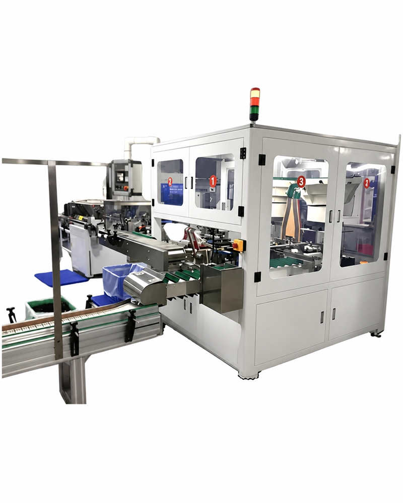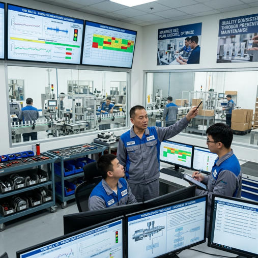
An unplanned tube mill stoppage doesn’t just pause production — it triggers a cascade: scrap accumulates at the restart, operators scramble to diagnose the fault, maintenance waits for a spare part, and the production schedule compresses everything downstream. For a cosmetic or pharmaceutical tube manufacturer running two or three shifts, a single unresolved fault can cost USD 800–2,500 per hour in lost output and wasted materials.
Most of those stoppages are preventable. This guide gives operators, maintenance technicians, and facility managers the practical diagnostic tools, maintenance protocols, and optimization frameworks to move from reactive firefighting to controlled, predictable production — across every major tube mill system, from welding and sizing to grinding and material feed.

Structured maintenance programs — not reactive repairs — are what separate 90% OEE lines from 70% OEE lines in tube packaging production. (Image: Unsplash)
1. Understanding Your Tube Mill: Core Components and Functions
Before any fault can be diagnosed efficiently, technicians need a clear mental model of how each major system contributes to the final tube — and how a failure in one zone cascades into defects downstream. Tube mills for cosmetic and pharmaceutical packaging are precision multi-station systems; treating them as black boxes is the fastest route to extended fault resolution times.
The Welding System
The welding unit is the most quality-critical station on any tube mill producing welded tube bodies. In plastic and laminate tube production, this is typically an ultrasonic or high-frequency welding system — a device that uses high-frequency vibration (20–40 kHz) or electromagnetic energy to generate friction heat precisely at the tube’s overlap seam, fusing the material without external heat application.
Key parameters controlling weld quality include frequency setting, amplitude (vibration intensity), weld pressure, weld time, and hold time after energy delivery. When any of these drift outside their validated range, the result appears downstream as seam leakage, delamination, or visible weld lines that fail aesthetic inspection at cosmetic brand customers.
Early warning signs of welding system degradation: inconsistent weld seam width across the tube run, increasing rejection rate on seal integrity tests, audible change in the weld head frequency signature, and surface discoloration or burn patterns near the seam — all of which typically precede a full weld failure by 4–12 production hours if unaddressed.
The Sizing and Forming Station
The sizing station controls the tube body’s final outer diameter (OD), roundness, and wall thickness uniformity after forming. For pharmaceutical and premium cosmetic applications, where tubes must fit precisely into standard dispensing closures, diameter tolerance is typically ±0.2mm or tighter — a specification that cannot be maintained with worn or misaligned dies.
The sizing system uses a calibrated die set — hardened steel or carbide inserts with a precisely machined bore — through which the formed tube passes under controlled pressure. Die wear is gradual and predictable, but the consequence is not: a die that is 0.3mm oversize produces tubes that feel loose in their caps, fail torque retention tests, and generate customer complaints about packaging performance that can be difficult to trace back to the equipment root cause without dimensional logs.
The Grinding and Finishing Assembly
In aluminum tube production, the grinding station removes the tube’s external weld bead to create a smooth, continuous surface — a prerequisite for both print registration quality and the clean surface appearance that pharmaceutical and premium cosmetic brands require. In plastic and laminate tube lines, a comparable finishing station handles surface cleaning and pre-treatment for decoration.
Grinding wheel performance deteriorates through two mechanisms: glazing (where the abrasive surface becomes polished and loses cutting ability — often caused by insufficient wheel speed or too-soft grit for the material) and loading (where tube material becomes embedded in the wheel surface — common with aluminum and soft alloys at high feed rates). Both conditions produce surface finish degradation that appears as chatter marks, uneven texture, or residual weld-bead visibility.
📖 Core Terminology: Tube Mill Systems
- OEE (Overall Equipment Effectiveness)
- A composite KPI measuring productive use of planned production time: OEE = Availability × Performance × Quality. World-class packaging equipment targets 85%+. Lines below 70% carry significant deferred maintenance.
- Ultrasonic Welding
- A seam joining process using high-frequency mechanical vibration (20–40 kHz) to generate friction heat at the bond interface — creating a strong weld without external heat application. Used in plastic and laminate tube body welding.
- Die Set
- A matched pair of hardened tool-steel inserts that define the tube’s final outer diameter in the sizing station. Die wear is the most common cause of diameter drift in tube production.
- Wheel Glazing
- A grinding wheel failure mode where the abrasive surface becomes polished and non-cutting — caused by incorrect wheel hardness selection or insufficient cutting speed. Produces deteriorating surface finish without visible wheel wear.
- MTBF (Mean Time Between Failures)
- The average operating time between unplanned failures for a specific component. Tracking MTBF for wear parts enables replacement scheduling before failure rather than after it.
- GMP (Good Manufacturing Practice)
- Regulatory standards governing pharmaceutical manufacturing environments, equipment qualification, and documentation — enforced by FDA (US), EMA (EU), and WHO globally. ISO 15378 extends GMP principles specifically to primary pharmaceutical packaging materials.
2. Welding Defects: Diagnosis and Solutions
Welding defects are the single most common quality escape in tube production — and the most consequential. A tube with a leaking seam that reaches a pharmaceutical patient carries regulatory liability. A cosmetic tube with a visible weld line that reaches a retail shelf triggers returns. Neither outcome is acceptable, and both are preventable with systematic diagnostic discipline.

Welding seam quality determines tube structural integrity and pharmaceutical compliance — even minor parameter drift can produce defects that only appear under burst-pressure testing. (Image: Unsplash)
Common Welding Defects and Their Causes
Seam Leakage and Porosity
What it looks like: Tubes fail burst-pressure or squeeze tests; visible pinholes or incomplete fusion zones under magnification; product seepage at the tube seam during accelerated stability testing.
Root causes in order of frequency:
- Incorrect energy/amplitude settings — the most common cause. Most weld parameter drift occurs after a material batch change (new laminate roll, different supplier) where the incoming material’s weld characteristics differ from the validated recipe. Solution: re-verify weld parameters with each new material batch, not just at scheduled calibration intervals.
- Moisture contamination in the tube material — laminate and plastic tube stock stored incorrectly absorbs ambient humidity. At elevated welding temperatures, moisture vaporizes at the weld interface, creating micro-voids that reduce bond strength by 15–30%. Maintain material storage at <50% relative humidity; allow cold-stored material to reach ambient temperature before production.
- Worn or contaminated weld tooling — ultrasonic horn wear or product/adhesive contamination on horn faces reduces energy transfer efficiency, requiring recalibration or replacement.
- Misaligned material overlap — if the tube blank’s overlap width deviates from specification (typically ±0.3mm), the weld zone geometry changes and energy distribution becomes uneven. Check material slitting tolerances on incoming inspection.
Step-by-step diagnostic procedure: (1) Collect 10 consecutive tubes showing the defect; (2) Measure overlap width on each — confirm within ±0.3mm spec; (3) Verify weld parameter settings against the validated recipe file; (4) Inspect horn face under 10× magnification for wear or contamination; (5) Test material moisture content with a moisture analyser; (6) Run a weld energy sweep (±5% from nominal in 1% increments) and destructively peel-test samples at each setting.
Weld Misalignment and Offset
What it looks like: Seam visibly offset from the tube’s longitudinal centerline; twisted or spiraling seam appearance along the tube length; uneven wall thickness at the seam zone.
Misalignment typically develops gradually rather than suddenly. The most common cause is progressive wear in the tube-forming mandrel support bearings — as bearing clearance increases, the mandrel develops a slight oscillation that introduces angular variation into the tube blank’s entry position at the weld station. A misalignment of 0.5mm at the weld station can produce a seam offset of 1.5–2mm in finished tube appearance — clearly visible and rejected by brand QC teams.
Realignment procedure: (1) Measure seam position on 20 consecutive tubes with a digital caliper; (2) Calculate the average offset and its direction; (3) Loosen and adjust the guide positioning upstream of the weld station in the opposite direction to the observed offset; (4) Run 50 test tubes and re-measure; (5) Tighten and document the corrected position in the setup record. If offset recurs within 4–8 hours, inspect mandrel support bearings for wear — offset recurrence indicates a mechanical root cause, not a setup issue.
Preventative Maintenance for Welding Systems
Regular Electrode / Horn Inspection and Replacement
For ultrasonic welding systems, the horn (also called sonotrode) is the component that transmits vibration energy to the weld zone. Horn wear is typically invisible to the naked eye at early stages — it manifests first as gradual changes in the weld energy readings required to achieve the same peel strength, which is why comparing actual energy consumption against the validated baseline is a more reliable wear indicator than visual inspection alone.
Inspection intervals should be tied to production volume: in high-speed tube production (200+ tubes/minute), inspect horn face condition every 40–60 production hours; in lower-speed operations, every 80–100 hours. Replace when: horn face shows visible erosion >0.1mm, peel strength at nominal settings drops below specification, or energy consumption to reach weld temperature increases by >10% from baseline.
Electrode Contact Tip Maintenance (ERW / High-Frequency Systems)
For ERW (Electric Resistance Welding) systems used in aluminum tube production, contact tips that deliver welding current to the tube seam require inspection every 8–12 production hours — the typical MTBF published by leading contact tip manufacturers. Contaminated tips increase electrical contact resistance, which reduces current density at the weld zone and produces incomplete fusion or porosity without any change in power settings. Cleaning protocol: use a non-conductive abrasive pad to remove oxide deposits from the contact face; never use metallic tools that can embed conductive particles. Replace tips when face erosion exceeds 0.5mm or contact resistance exceeds 20% above baseline.
3. Sizing Misalignment: Preventing Dimensional Inconsistencies
In pharmaceutical tube packaging, dimensional compliance is not optional — it is a regulatory requirement. A tube that does not seat correctly in its dispensing closure, or whose shoulder does not mate with its cap torque specification, is a non-conforming product that must be rejected, documented, and investigated under GMP procedures. The cost of a dimensional non-compliance event extends well beyond the scrap value of the affected batch.
Common Sizing Issues and Root Causes
Diameter Variation and Out-of-Spec Tubes
Diameter variation in tube production follows two distinct patterns, each with a different root cause. Gradual drift — where diameter slowly increases or decreases over a production run — is almost always die wear or progressive pressure change in the sizing system. Sudden step-change — where diameter jumps to a new value and stabilizes — indicates a setup error, an abrupt pressure change (often a hydraulic leak or pneumatic pressure drop), or a material change mid-reel.
Detection requires systematic measurement, not reliance on operator visual assessment. The recommended protocol for pharmaceutical and premium cosmetic tube production: measure OD with a calibrated digital micrometer (resolution 0.001mm) on five tubes every 30 minutes during the production run, log values against the control chart, and initiate investigation if any single reading exceeds ±0.15mm from nominal or if three consecutive readings trend in the same direction (indicating developing drift before the tolerance limit is reached).
Wall Thickness Inconsistencies
Wall thickness variation affects tube performance in ways that may not be immediately visible. A tube with a thin-wall zone at the shoulder junction fails earlier in drop testing, shows unsatisfactory torque retention on the cap, and may crack or split under the compressive load of normal consumer use. In pharmaceutical tubes containing pressurized products (aerosol-adjacent formats), wall thickness consistency is a direct safety consideration.
The primary cause of wall thickness variation is eccentric tube positioning in the sizing station — where the tube bore is not perfectly centered with the die bore, resulting in more material compressed on one side than the other. This eccentricity develops from mandrel wear, guide roller adjustment errors, or material tension inconsistencies in the feed system. Correction requires a mandrel-centering procedure with dial indicator measurement — a 15-minute operation that eliminates the root cause, versus the 2–4 hours of production time that wall thickness investigation and documentation consume when the defect reaches inspection.
Sizing System Calibration and Alignment
Die Condition Assessment and Replacement
| Die Material | Typical Service Life | Material Processed | End-of-Life Indicator | Replacement Trigger |
|---|---|---|---|---|
| Tool Steel (D2) | 200–280 hrs | Aluminum tubes | OD drift >0.10mm from nominal | Monitor from 180 hrs |
| Tungsten Carbide | 400–600 hrs | Aluminum / hard alloys | Surface scoring visible under 10× magnification | Replace at 0.15mm bore oversize |
| Chrome-Plated Steel | 150–220 hrs | Plastic (PE/PP) tubes | Chrome delamination or surface pitting | Replace immediately on pitting |
| Nitride-Treated Steel | 300–420 hrs | Laminate (ABL/PBL) | Gradual surface dulling; increased friction noise | Monitor from 260 hrs |
Pressure System Optimization
Hydraulic and pneumatic pressure consistency in the sizing station is as important as die condition — a well-conditioned die operating under fluctuating pressure produces the same diameter variation as a worn die operating under stable pressure. Pressure drop events — where system pressure drops by >5% during the machine cycle — are the most common undiagnosed cause of periodic diameter variation (tubes that are intermittently out-of-spec rather than consistently drifting).
Install a data-logging pressure transducer on the sizing station’s pressure supply and record pressure traces across 10 complete machine cycles. Any pressure drop coincident with a tube diameter measurement above the upper control limit confirms a pressure system root cause. Common fixes: replace accumulator bladder (if pressure drops during the high-demand part of the cycle), inspect and tighten all hydraulic line connections (leak-induced pressure loss), and replace worn pump seals (which reduce maintained pressure under load).
4. Grinding Inconsistencies: Achieving Superior Surface Finish
Surface finish quality is where tube mill performance becomes directly visible to end customers. A cosmetic brand’s premium aluminum tube with an uneven, matte-inconsistent surface will be rejected at incoming inspection before a single tube is printed. A pharmaceutical tube with chatter marks creates a rough surface that makes label adhesion inconsistent — a potential regulatory non-conformance if batch identification labels don’t adhere reliably. Grinding is not an afterthought operation: it is the final step that determines whether the tube is saleable.
Common Grinding Problems and Solutions
Uneven Surface Finish and Chatter Marks
Chatter marks — a repeating pattern of light and dark bands across the tube surface, typically spaced 1–5mm apart — are the most common and most visually obvious grinding defect. They occur when the grinding wheel’s contact with the tube surface is intermittent rather than continuous, producing alternate cutting and non-cutting moments that leave the regular banding pattern.
Diagnostic sequence for chatter marks:
- First, check wheel condition: dress the wheel and test with the same feed rate. If chatter disappears, the root cause was wheel glazing or loading.
- If chatter persists after dressing, reduce feed rate by 10% increments until chatter disappears — this confirms the feed rate was above the stable cutting threshold for the current wheel specification.
- If chatter persists at reduced feed rate, check spindle bearing play: measure radial runout at the grinding wheel arbor with a dial indicator. Runout exceeding 0.02mm indicates bearing wear that requires replacement.
- Verify workpiece support rigidity: loose or worn tube-support guides allow tube vibration during grinding, producing chatter even with a perfect spindle and wheel.
Grinding Wheel Glazing and Loading
Glazing and loading are both wheel degradation modes, but they have opposite causes and require different responses. Glazing occurs when the abrasive grains become polished — the wheel looks shiny and cutting efficiency drops sharply, often causing heat build-up and thermal discoloration of the tube surface. Loading occurs when workpiece material becomes embedded in the wheel’s pores — the wheel looks clogged, cutting becomes inefficient, and surface finish deteriorates rapidly. Both conditions are corrected by wheel dressing, but preventing recurrence requires addressing the root cause: glazing indicates too-soft wheel specification for the material; loading indicates too-high feed rate or insufficient coolant flow.
Dressing procedure: Use a single-point diamond dresser at the manufacturer’s specified traverse rate and depth of dress (typically 0.02–0.05mm per pass). Take 2–3 passes to restore a clean, sharp abrasive face. Run a test piece and verify surface finish before resuming production. Log the dressing event (date, time, number of passes, condition before dressing) — dressing frequency trends are the leading indicator of wheel specification mismatch or process parameter drift.
Grinding Wheel Management and Optimization
Wheel Selection and Specifications
| Tube Material | Recommended Grit Range | Wheel Hardness | Typical Service Life | Key Selection Note |
|---|---|---|---|---|
| Aluminum tubes | K–M (medium) | Soft–Medium | 40–80 hrs | Soft bond prevents loading in ductile aluminum |
| Steel / tin tubes | H–J (fine) | Hard | 20–40 hrs | Hard bond maintains cutting edge on ferrous materials |
| Composite / laminate | L–N (medium–coarse) | Medium | 30–60 hrs | Verify compatibility with laminate adhesive layer |
| Coated aluminum | K–L (medium-soft) | Soft–Medium | 35–70 hrs | Avoid hard bonds that risk coating adhesion damage |
Wheel Dressing and Maintenance Schedules
Dressing frequency is one of the most facility-specific variables in tube mill maintenance — it depends on material type, wheel specification, feed rate, and production volume. The correct approach is to establish your baseline dressing interval empirically: log surface finish measurements every 2 hours; record the production hours elapsed when surface finish first begins to degrade; set your dressing schedule at 80% of that interval to ensure you are dressing before quality impact rather than after.
Most aluminum tube production facilities find that grinding wheels require dressing every 20–40 production hours and complete replacement every 40–80 hours. This means a well-run facility should have a minimum of 2–3 spare wheels per grinding station in stock at all times — a spare-parts investment of typically $400–$1,200 per station that eliminates the risk of extended production stoppage from wheel failure without a replacement available.
5. Material Feed and Extrusion Issues
Feed system problems are the most upstream source of tube quality defects — and because they occur before the forming and welding stations, a feed issue that goes undetected for 30 minutes can contaminate an entire production run with dimensional or structural defects that only become visible at final inspection. Early detection requires operators who understand what normal feed system behavior looks and sounds like, so they notice deviations immediately.

Material feed consistency — moisture content, feed rate stability, and contamination control — directly determines the dimensional and structural quality of every tube produced downstream. (Image: Unsplash)
Common Material Feed Problems
Inconsistent Material Flow and Bridging
Bridging (where granules or pellets form an arch across the hopper outlet, stopping material flow while the auger below continues to rotate) is the most common feed system fault in plastic tube extrusion lines. It is particularly prevalent with irregular-shaped granules, high-fat or surface-treated materials, and in high-humidity environments where pellet surface tackiness increases.
A bridging event that is not immediately detected results in: a period of starved extrusion producing undersized, thin-walled tubes; followed by a surge when the bridge collapses and excess material enters the extruder; followed by oversized, thick-walled tubes — all of which must be scrapped and traced in the production record. Detection: Most modern extrusion lines include a motor current monitor on the extruder drive — current drops sharply during starvation and spikes at surge. If your line does not have this monitoring, add a simple current data logger to the extruder motor circuit; the data it generates will identify feed system faults within minutes of occurrence rather than at end-of-shift inspection.
Material Degradation and Contamination
Contamination in tube-grade polymer material manifests as black specks, gels (unmelted polymer lumps), or discoloration in the tube wall — visible at final inspection and rejected by every cosmetic and pharmaceutical customer. The contamination sources in order of frequency are: material storage contamination (open bags stored in dusty environments, or bags stored on pallets exposed to moisture); hopper and auger contamination from previous material or cleaning residue; and degraded material from overlong residence time in the extruder barrel (typically caused by extended production stops without purging the barrel).
Best practice for contamination prevention: seal all material bags immediately after use; implement a first-in-first-out material rotation policy; purge the extruder barrel with a virgin neutral grade resin whenever production stops exceed 20 minutes; and conduct weekly hopper cleaning with a solvent wipe before restarting after material grade changes.
Feed System Optimization
Hopper and Auger Maintenance
Auger wear — the gradual erosion of the auger flight edges — reduces volumetric feed accuracy over time and is one of the most under-monitored wear points in tube extrusion lines. A worn auger running at the same RPM as a new auger delivers 5–15% less material per revolution, causing a gradual drift toward undersize and thin-wall tubes that is often attributed to material batch variation rather than equipment wear. Measure auger flight-to-barrel clearance quarterly; replace the auger when clearance exceeds manufacturer’s specification by 0.5mm or feed rate calibration requires a >10% RPM increase to maintain target output.
Feed Rate Calibration
Calibrate feed rate at the start of each production campaign and after any material batch change. The calibration procedure: run the feed system for 60 seconds at the nominal setpoint; collect and weigh the discharged material; compare against the target mass for that time period at that RPM. If actual output is >3% from target, adjust the RPM setpoint and repeat until within tolerance. Document the calibration result and the corrected setpoint — this data, trended over time, provides the leading indicator of auger wear before it affects tube quality.
6. Preventative Maintenance: Reducing Downtime and Extending Equipment Life
The financial case for preventative maintenance (PM) in cosmetic and pharmaceutical tube production is unambiguous. Rolling mill vibration monitoring studies show that facilities implementing structured PM programs report 45–65% fewer unplanned breakdowns and 60% lower emergency repair costs compared to reactive-maintenance operations. In tube production specifically, each percentage point of OEE improvement on a mid-size automatic line adds approximately 8,000–15,000 additional saleable tubes per month.
Daily Maintenance Checklist
Pre-Production Inspection Procedures
A pre-production inspection completed in 10–15 minutes at shift start prevents the majority of quality-related production stoppages. The inspection should establish a performance baseline — if the machine does not meet baseline at startup, the issue is corrected before production begins, not discovered mid-run after defective tubes have been produced.
- Verify weld parameter settings against the active product recipe file — confirm no unauthorized changes from previous shift
- Check sizing die condition — visually inspect for scoring, cracking, or contamination; verify die is correctly seated and fasteners are torqued to specification
- Confirm hydraulic/pneumatic operating pressure is at the set-point for this product — check pressure gauge readings before starting
- Inspect grinding wheel condition — no visible loading or glazing; correct guard clearance; spindle rotation smooth with no audible bearing noise
- Verify material hopper is loaded with the correct material grade and lot — confirm matches production order
- Run 10 startup tubes; measure OD, wall thickness, and seam integrity; confirm all within specification before clearing for full production
- Log baseline readings (pressure, temperature, extruder current, weld energy) in the shift production record
During-Production Monitoring
In-process monitoring converts the production run from an unobserved process into a controlled, documented process. At minimum, the following checks should occur at defined intervals throughout every production run:
- Every 30 minutes: dimensional check (5-tube OD and wall thickness sample); log against control chart
- Every hour: surface finish visual inspection on 3 tubes from each shift; note any developing chatter pattern
- Every 2 hours: weld integrity destructive test (peel test on 2 tubes); compare peel force against minimum specification
- Every 2 hours: extruder motor current reading — trend against baseline to detect developing feed issues
- Continuous: operator monitoring of audible machine signature — unusual noises are always investigated immediately
Weekly and Monthly Maintenance Tasks
Component Inspection and Lubrication
| Component | Maintenance Task | Interval | Lubricant / Specification | Typical Time |
|---|---|---|---|---|
| Forming mandrel bearings | Grease repack | Weekly | NLGI Grade 2 lithium complex | 20 min |
| Sizing station guide rollers | Inspect for wear; oil lubrication | Weekly | ISO VG 32 machine oil | 15 min |
| Grinding spindle bearings | Grease repack; runout check | Monthly | High-speed spindle grease (NLGI 2 HT) | 45 min |
| Hydraulic fluid | Level check and visual contamination test | Weekly | ISO VG 46 anti-wear hydraulic fluid | 10 min |
| Drive chains / belts | Tension check; visual wear inspection | Weekly | Chain spray lubricant | 15 min |
| Weld tooling contact faces | Clean with non-abrasive solvent; inspect for wear | Weekly | Isopropyl alcohol | 20 min |
| All hydraulic seals | Visual leak inspection; replace on seepage | Monthly | OEM-specified seal kits | 30–90 min |
Calibration Verification and Testing
Monthly calibration verification — checking that the machine’s measuring and control systems still report accurate values — is the maintenance task most consistently omitted under production pressure and most consistently identified in GMP audit findings for pharmaceutical tube manufacturers. Calibration drift is invisible until it causes a quality event; by then, the production records generated with out-of-calibration instruments may need to be retrospectively evaluated, which is a significant compliance burden.
The minimum monthly calibration verification scope: (1) Verify sizing die gauge against traceable reference gauge blocks; (2) Calibrate weld energy sensors against calibrated reference meters; (3) Verify hydraulic pressure transducers against reference gauges; (4) Check extruder temperature controllers against calibrated thermocouples. Document all results with the actual values measured, the reference standard used, its calibration certificate number, and the technician’s name and date. This documentation satisfies both GMP audit requirements and provides the trend data needed to detect calibration drift before it reaches the 20% deviation threshold that triggers regulatory concern.
7. Troubleshooting Systematic Approach: Step-by-Step Problem-Solving
The difference between a maintenance team that resolves faults in 45 minutes and one that takes 4 hours is rarely technical knowledge — it is methodology. A structured approach prevents the most common troubleshooting time-waster: immediately implementing the first plausible solution rather than confirming the root cause first, only to find that the “fix” addressed a symptom while the root cause continued to produce defects.
▶ Watch: Tube Mill Line Device Maintenance — a practical walkthrough of key maintenance procedures to keep production equipment running at peak performance.
The Five-Step Troubleshooting Process
Problem Identification and Documentation
Before touching anything: collect 10 defective samples; take photographs; record the time the defect first appeared, the production parameters at that moment, and any events in the preceding 2 hours (material batch change, shift change, machine restart, maintenance work). The information gathered here determines whether the next 30 minutes are spent finding the root cause or chasing symptoms.
System Isolation and Analysis
Identify which station is generating the defect by tracing the tube through the process: does the defect exist before the grinding station? Before the sizing station? The answer eliminates all downstream stations from the investigation. Review the last maintenance records for the implicated station. Check whether recent adjustments, replacements, or calibration changes coincide with the defect onset.
Solution Implementation and Testing
Implement one corrective action at a time. Changing multiple parameters simultaneously is the most common troubleshooting error — it makes it impossible to identify which change resolved the issue, which prevents effective documentation and recurrence prevention. Run a minimum of 50 test tubes after each corrective action before evaluating success; some defects have cycle-time-dependent characteristics that require a production run of sufficient length to manifest.
Verification and Validation
Confirm the problem is resolved through both quantity and variety of verification testing. Run a 200-tube extended test and measure the full quality parameter set — not just the parameter that appeared in the defect. Defect-fixing adjustments sometimes solve one issue while introducing another that only appears at scale. Extend the test to 500 tubes if the defect was intermittent (appearing in fewer than 10% of tubes) — intermittent defects require larger sample sizes to confirm resolution with statistical confidence.
Prevention and Documentation
The final step is the one most often omitted under production schedule pressure — and the one that determines whether the same fault recurs in 3 months. Document the root cause, the corrective action taken, the verification results, and any changes to the maintenance schedule or process parameters that will prevent recurrence. Update the troubleshooting knowledge base. If a component reached end of life earlier than expected, adjust the replacement schedule for that component across all lines. This step converts a reactive repair into a permanent improvement.
Creating a Knowledge Base
A fault history log — even a simple spreadsheet recording date, fault description, root cause, corrective action, and resolution time — is one of the highest-ROI investments available to a tube mill maintenance operation. Within 12 months of consistent use, a fault log provides:
- A reference that reduces average fault resolution time by 30–50% for recurring fault types
- The data needed to identify chronic issues (faults that recur monthly are almost always PM schedule gaps or design weaknesses that deserve engineering attention)
- Training material that enables new technicians to reach operational proficiency in 50–60% of the time required without documented reference
- The audit trail required for GMP compliance demonstration in pharmaceutical packaging operations
For manufacturers operating multiple tube lines or multiple facilities, sharing the fault log across sites is a straightforward multiplier: a fault resolved at one facility in 20 minutes becomes a fault resolved at all facilities in 20 minutes rather than each site independently spending 4 hours rediscovering the same solution. Miyoda Packaging Machinery’s complete tube production line range is supported by technical documentation specifically designed to form the foundation of this kind of multi-site knowledge management system.
8. Optimization Strategies: Maximizing Performance and Efficiency
Troubleshooting restores performance to its baseline. Optimization moves the baseline itself — systematically improving throughput, reducing waste, and tightening quality beyond what the original production setup achieved. For cosmetic and pharmaceutical tube manufacturers facing margin pressure from rising material costs and customer quality expectations, optimization is not a one-time project; it is an ongoing operational discipline.
Production Parameter Optimization
Speed and Throughput Enhancement
Speed increases in tube mill production must be approached as controlled experiments, not as simple dial adjustments. The reason: every mechanical system in a tube mill has an upper speed threshold above which its performance degrades — weld quality deteriorates, dimensional scatter widens, surface finish degrades. These thresholds are not printed in machine manuals; they are discovered empirically and they change as the machine ages and wear accumulates.
The safe speed-increase protocol: increase line speed by 5% increments from the current setpoint; run 500 tubes at each speed increment; measure the full quality parameter set (OD, wall thickness, weld peel strength, surface finish); confirm all within specification before increasing further. Most well-maintained tube mills can sustain 10–15% above their initial commissioning speed after 12 months of operation — not because the machine has improved, but because the team’s understanding of the machine’s optimal parameters has deepened.
Quality Consistency Improvements
Statistical Process Control (SPC) — the use of control charts to monitor process measurements and detect developing variation before it reaches specification limits — is the industry standard methodology for quality consistency improvement in regulated packaging. FDA cGMP regulations for pharmaceutical packaging explicitly reference statistical monitoring as an element of process validation. For cosmetic tube producers serving major brand customers, SPC implementation is increasingly an audit requirement in supplier qualification programs.
The practical implementation is straightforward: measure OD on 5 tubes every 30 minutes; plot the measurements on an X-bar chart with control limits set at ±3 standard deviations from the process mean. When a point falls outside the control limits or when 8 consecutive points fall on the same side of the centerline, investigate before the next quality measurement. This approach detects developing drift before defective tubes are produced — converting quality control from inspection (detecting defects after creation) to prevention (stopping defects before they occur).
Efficiency and Cost Reduction
Understanding Where Downtime Comes From
Tube Mill Downtime Root Cause Distribution
Source: Industry maintenance benchmark analysis for cosmetic and pharmaceutical tube production lines.
Energy Consumption Optimization
Energy costs in tube mill production are typically underestimated as a line-item because they are reported as a facility-level utility bill rather than allocated to individual production lines. A typical mid-size aluminum tube production line consumes 35–65 kW during active production and 12–18 kW during idle/standby periods. If a line runs 20 hours/day with 4 hours of scheduled idle time (breaks, shift changes, changeovers), the idle period consumes approximately 50–70 kWh per day — roughly 15–20% of total daily energy consumption for zero productive output.
Implementing an automated power management sequence that transitions grinding spindles, extruder heaters, and hydraulic system pumps to low-power standby mode during scheduled idle periods — triggered by the line’s PLC when the production sequence is paused — typically recovers 12–18% of total daily energy consumption. At an industrial electricity rate of $0.10–0.15/kWh, the annual saving from this single change on a single line is $2,000–$5,000. It requires only PLC programming changes, not capital investment.
Material Waste Reduction
The most impactful single intervention for material waste reduction in tube production is reducing startup scrap — the tubes produced during machine startup and stabilization that must be scrapped before the process reaches steady-state specification. A manual tube mill typically produces 20–40 startup scrap tubes per production run. An automated line with recipe-based parameter recall produces 5–10 startup scrap tubes. The difference — 15–30 tubes per run, multiplied by 5–8 production runs per shift, across 250 production days per year — is 19,000–60,000 tubes per line per year in recoverable startup scrap: $3,800–$18,000 in material cost, assuming $0.10–$0.30 per tube material cost.
9. Technology and Tools for Modern Tube Mill Management
Monitoring and Diagnostic Equipment
Real-Time Production Monitoring Systems
Modern tube mills equipped with sensor networks — pressure transducers, temperature sensors, vibration accelerometers, and current monitors on all major drives — generate a continuous data stream that is the foundation of proactive maintenance. The data itself has limited value without a monitoring platform that displays it in real time, applies control limit logic to generate alerts, and stores it historically for trend analysis.
Entry-level real-time monitoring can be implemented with a data logger and basic SCADA (Supervisory Control and Data Acquisition) software for $5,000–$15,000 per line — a fraction of the cost of a single extended unplanned downtime event on a high-speed tube production line. For manufacturers evaluating complete production line upgrades, Miyoda Packaging Machinery’s tube extrusion line systems include integrated sensor monitoring and parameter logging as a standard feature of their control architecture.
Predictive Maintenance Technologies
Vibration analysis is the most mature and widely deployed predictive maintenance technology for rotating equipment. A bearing developing inner-race fatigue generates a characteristic vibration frequency signature detectable by an accelerometer up to 200–400 operating hours before catastrophic failure. For tube mill spindle bearings — which, when they fail, damage grinding wheels, tube support guides, and in some cases the spindle housing itself — this advance warning translates directly into a scheduled replacement during a planned maintenance window versus an emergency repair requiring days and possibly expensive secondary damage repair.
Thermal imaging (using an infrared camera to detect abnormal heat patterns in electrical panels, motor windings, and hydraulic systems) identifies developing faults in electrical and thermal systems that vibration analysis does not reach. A thermal imaging survey conducted quarterly on each tube mill line — a 30–45 minute operation with a handheld thermal camera — consistently identifies 2–4 developing faults per survey in facilities that have not previously implemented this inspection, according to industrial thermal imaging service providers.
Software Solutions and Data Management
Production Management Software
A CMMS (Computerized Maintenance Management System) — software that manages maintenance schedules, work orders, spare parts inventory, and maintenance records — is the operational infrastructure that makes a PM program sustainable. Without a CMMS, maintenance schedules exist on paper or in spreadsheets that are easily missed under production pressure; with a CMMS, maintenance tasks are automatically scheduled, reminder-triggered, and documented in a searchable, auditable database.
For pharmaceutical tube manufacturers, a CMMS is not just operationally useful — it is essential for demonstrating GMP compliance. FDA GMP compliance for maintenance teams requires that all maintenance activities affecting product quality are documented, that calibration records are maintained and traceable to reference standards, and that equipment history is available for retrospective review in the event of a product non-conformance investigation. A well-configured CMMS satisfies all of these requirements automatically.
Troubleshooting Support Resources
The quality of troubleshooting support from equipment manufacturers has become a meaningful differentiator in the tube mill market. Remote support capabilities — where an equipment manufacturer’s engineer can connect to the machine’s control system via a secure VPN connection, review live parameter data, and guide the on-site technician through a diagnostic procedure — are now standard offerings from leading manufacturers. This capability has documented resolution time advantages: faults that would require a 48–72 hour wait for an on-site service visit are often diagnosed and resolved in 2–4 hours via remote connection.
When evaluating equipment suppliers, ask specifically: Does the machine’s control system support remote diagnostics? What is the average response time for remote support inquiries? Are digital interactive manuals and troubleshooting decision trees available, or only paper documentation? The answers to these questions will determine what your maintenance team’s experience is at 2am during a shift that is running a critical pharmaceutical production campaign.
10. Industry Standards and Compliance Considerations

Regulatory compliance documentation is not a bureaucratic burden — it is the audit trail that protects manufacturers from liability and enables pharmaceutical contracts. (Image: Unsplash)
Quality Standards and Certifications
ISO and Industry-Specific Standards
ISO 9001:2015 — the global quality management system standard — provides the framework for documented, process-based quality management that is the baseline requirement for supplying major cosmetic brands. ISO 9001 does not prescribe specific manufacturing processes; it requires that processes are defined, controlled, measured, and continuously improved. A tube mill operation implementing the troubleshooting and maintenance systems described in this guide is, in effect, building the operational infrastructure that ISO 9001 certification formalizes.
ISO 15378:2017 extends GMP principles specifically to primary pharmaceutical packaging materials manufacturing — directly applicable to tube mills producing pharmaceutical primary packaging. ISO 15378 certification requires that manufacturing equipment is qualified, maintained to defined schedules, calibrated against traceable references, and that all maintenance activities are documented in a format suitable for regulatory audit. Achieving ISO 15378 certification requires no technologies or procedures beyond those described in this guide — but it requires that those procedures are documented, consistently followed, and subject to internal audit.
Material and Safety Certifications
Tube materials used in pharmaceutical primary packaging must comply with USP <661> Plastic Packaging Systems and Their Materials of Construction, which defines testing requirements for chemical compatibility, extractables, and material identification. The tube mill’s role in material compliance is to ensure that processing conditions (temperature, pressure, weld energy) do not alter the material’s chemical composition — which is why weld parameter validation and temperature monitoring are GMP requirements, not just quality preferences.
For cosmetic tube production, material compliance requirements are defined by the brand customer’s product specification and regional regulations (EU Cosmetics Regulation 1223/2009 for EU-bound products; FDA’s Modernization of Cosmetics Regulation Act (MoCRA) for US-bound products). The common thread: tube materials that contact the product must be chemically compatible, and the production process must not introduce contaminants. Both requirements are directly supported by the cleaning, contamination control, and process parameter management practices described throughout this guide.
Documentation and Record-Keeping
Maintenance Records and Traceability
The documentation requirements for pharmaceutical tube manufacturing are specific and audited. The minimum record set that satisfies both FDA 21 CFR 211 and ISO 15378 requirements includes: equipment qualification records (IQ/OQ/PQ documentation confirming the equipment was installed correctly, operates as specified, and produces product within specification); calibration records for all measurement and control instruments; maintenance activity logs with dates, technician identification, work performed, and parts replaced; and non-conformance reports for any quality event with root cause analysis and corrective action documentation.
For cosmetic tube manufacturers, maintaining this documentation level — even where not legally required — provides a competitive advantage in brand customer audits, where detailed process control documentation increasingly differentiates capable suppliers from commodity vendors. The time investment is approximately 30–45 minutes per production shift for complete documentation; the return is access to pharmaceutical and premium cosmetic contracts that require this evidence of process control maturity.
Quality Control Documentation
Every production batch should generate a batch record that documents: production order number, tube specification, material batch numbers, production parameters (weld energy, sizing pressure, grinding speed), in-process quality measurement results with operator identification, non-conformance events and their resolutions, and final release or rejection decision. This documentation serves three functions: it provides the traceability required for pharmaceutical batch recall management; it provides the data needed for trend analysis and process improvement; and it demonstrates to auditors that quality is a managed process, not an assumed outcome.
Building a Culture of Excellence in Tube Mill Operations
The troubleshooting knowledge and maintenance protocols in this guide are practical tools — but their impact depends on the operational culture in which they are deployed. A facility where operators take pride in their machines, maintenance technicians document their findings consistently, and production managers treat PM schedule compliance as seriously as output targets will systematically outperform a facility with better equipment but lower operational discipline.
The measurable outcomes of this operational approach are specific: OEE above 85%, scrap rates below 2%, fault resolution times under 60 minutes for the majority of common faults, and a compliance documentation record that opens pharmaceutical and premium cosmetic contracts. These outcomes are not reserved for large, well-funded operations — they are available to any manufacturer that implements systematic maintenance and troubleshooting discipline regardless of equipment vintage or facility size.
For manufacturers planning equipment investments alongside their maintenance improvement programs, working with a supplier who understands the operational demands of cosmetic and pharmaceutical tube production is essential. Miyoda Packaging Machinery’s tube filling and sealing guide provides complementary technical depth on downstream operations, and the engineering team is available for facility-specific consultation on both new equipment specification and optimization of existing production lines.
The key principle: treat your tube mill as a precision instrument that delivers consistent results when it receives consistent care — and as a capital asset whose financial return is determined as much by maintenance discipline as by initial specification. The investment in structured troubleshooting and preventative maintenance consistently delivers returns of 4–6× in avoided downtime costs alone, before quality and compliance benefits are factored in.
🔧 Ready to Optimize Your Tube Mill Operations?
Contact our team of packaging machinery experts for a personalized consultation on your specific production challenges. We provide on-site training, maintenance planning, technical assessment, and support services designed to maximize your equipment’s performance and longevity.
Schedule Your Free Equipment Assessment →For distributors and agents: access our complete resource library and technical support network to enhance your value proposition. Trusted by 500+ cosmetic and pharmaceutical manufacturers worldwide.